● INTRODUCTION
The visualization of the great vessels is currently part of the basic obstetric ultrasound examination, and thus a good understanding of the anatomic relationship of the great vessels and the related ultrasound views is essential to the successful performance of the obstetric ultrasound examination (1, 2). Many major congenital heart anomalies, especially the conotruncal type, may escape prenatal detection if the ultrasonographic cardiac evaluation is limited to the four-chamber view. Adequate visualization of the great vessels on ultrasound includes demonstration of the origin of the aorta and pulmonary artery from the left and right ventricles, respectively, vessel size, anatomic relationship, and alignment and course of the great vessels (1). Multiple cardiac ultrasound imaging planes are thus required for the evaluation of the great vessels. The anatomy of the great vessels was reviewed in detail in Chapter 5. In this chapter, we present the various ultrasound diagnostic planes that are required for a comprehensive prenatal evaluation of the great vessels. The three-vessel trachea view, an axial (transverse) view obtained in the upper mediastinum, has received special attention in the past several years (1, 3) and thus will be presented in detail in Chapter 9. Furthermore, a comprehensive evaluation of the fetal venous system will be presented in Chapter 10.
The orientation and access to the fetal heart differ from postnatal scanning. In this chapter, we will rely on the anatomic approach of various diagnostic planes as it relates to the anatomic long axis of the fetus (fetal spine), rather than the long axis of the heart itself. Transverse views are therefore obtained from a transverse, or near-transverse, orientation of the ultrasound transducer to the fetal spine, and sagittal views are obtained from a sagittal or parasagittal orientation of the ultrasound transducer to the fetal spine. Cardiac views that are neither near transverse nor near sagittal are referred to as oblique views. The authors believe that this approach is best adapted to fetal cardiac imaging (4, 5).
● SCANNING TECHNIQUE FOR AXIAL VIEWS OF THE OUTFLOW TRACTS
1. Determine the fetal situs (see Chapter 6).
2. Obtain a four-chamber view of the fetal heart (see Chapter 7).
3. From the four-chamber view plane (Fig. 8.1), the left ventricular outflow tract (the aorta), referred to as the five-chamber view, can be imaged by a slight tilt or rotation of the medial aspect of the transducer in the direction of the fetal head (Fig. 8.1).
4. From the four-chamber view, the pulmonary trunk origin from the right ventricle can be visualized in the three-vessel view, by sliding the transducer cranially while maintaining the transverse orientation in the chest (Fig. 8.1).
5. From the three-vessel view, the transverse view of the arterial duct can be obtained by a slight cranial tilt of the transducer (Fig. 8.1).
6. From the transverse view of the arterial duct, the transverse view of the aortic arch can be obtained by a slight cranial slide of the transducer (Fig. 8.1).
7. From the transverse view of the aortic arch, the three-vessel trachea view can be obtained by slightly angulating the transducer caudally and to the left (Fig 8.1). The three-vessel trachea view is not presented in this chapter, as it will be discussed in more detail in Chapter 9.
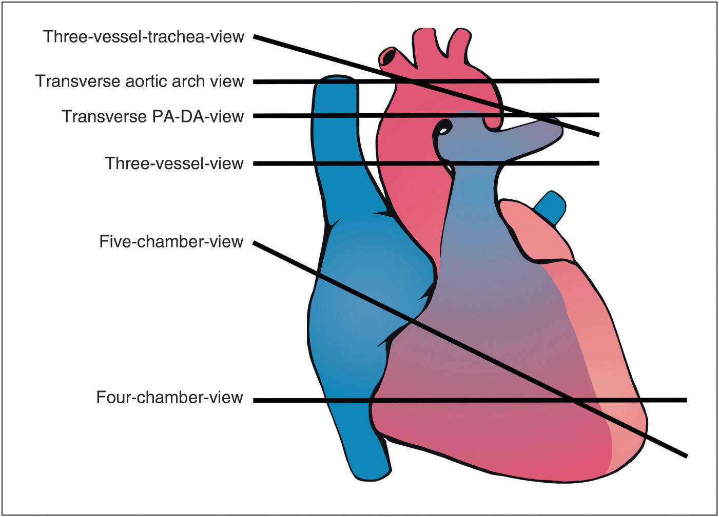
Figure 8.1: Schematic drawing showing the anatomic relationship of the diagnostic transverse planes of the fetal heart. See text for details. PA, pulmonary artery; DA, ductal arch.
The Five-Chamber View
The five-chamber view is obtained in a transverse plane cephalad to the four-chamber view with a slight angulation of the transducer toward the fetal head (Fig. 8.1), thus allowing for a full display of the ascending aorta (Fig. 8.2). The aortic outflow accounts for the fifth component of the five-chamber view, which demonstrates the left ventriculoarterial connection and the perimembranous and muscular ventricular septa (see for anatomic specimens Figs. 5.11 and 5.16). The ascending aorta arises in the midportion of the heart between the two atrioventricular valves in a left-to-right orientation (in the direction of the right shoulder) (Figs. 8.2 and 8.3). A wide angle is seen between the direction of the ventricular septum and the anterior wall of the ascending aorta (Fig. 8.2), an important anatomic observation that is commonly absent in conotruncal anomalies (more parallel orientation with the ventricular septum). The ascending aorta runs between the two atria before it forms the transverse aortic arch. A critical anatomic component of the five-chamber view is the continuity of the posterior wall of the aorta with the mitral valve (fibrous–fibrous continuity) and the continuity of the anterior wall of the aorta with the ventricular septum (fibrous–muscular continuity) (Fig. 8.2). This continuity is disrupted in the presence of aortic override (see Chapter 25). The five-chamber view displays the inflow, trabecular, and outflow components of the left ventricle and a portion of the trabecular right ventricle. Tricuspid valve and right ventricular inflow are often not seen in the five-chamber view. The two superior pulmonary veins enter the posterior wall of the left atrium at the five-chamber view level (Fig. 8.2).
The Three-Vessel View
The three-vessel view, also called transverse pulmonary trunk view, is obtained in a transverse plane of the fetal upper thorax (Figs. 8.1 and 8.4). The three-vessel view demonstrates the main pulmonary trunk in an oblique section arising from the right ventricle and bifurcating into both right and left pulmonary arteries (Fig. 8.4) (see for anatomic specimens Fig. 5.13). The ascending aorta and the superior vena cava are seen in transverse sections next to the pulmonary artery (Fig. 8.4). These three vessels are arranged in an oblique line with the pulmonary artery in the most anterior position, the superior vena cava in the most posterior position, and the aorta in between (Fig. 8.4). The pulmonary artery is the largest in size and the superior vena cava is the smallest. Measuring for pulmonary artery dimensions in this plane is not advisable given an oblique orientation of the vessel. The pulmonary artery arises anteriorly in the chest and angles posteriorly to the left of the spine (Fig. 8.4). The left pulmonary artery follows the same course as the main trunk, whereas the right pulmonary artery originates at a right angle and runs behind the ascending aorta and the superior vena cava (Fig. 8.4). In the posterior aspect of the three-vessel view plane, the descending aorta is to the left of the spine, a small normal azygos vein is to the right of the spine, and the two main bronchi are noted slightly anterior to the esophagus when imaging is obtained in high resolution (Fig. 8.4). The trachea is not seen at the three-vessel view plane, as it is located at a slightly higher level in the mediastinum at the three-vessel trachea view. The three-vessel view plane is helpful in the assessment of conotruncal abnormalities. Abnormalities may involve vessel size, vessel alignment, vessel arrangement, vessel number, and location of descending aorta (3). Color Doppler can also be used to evaluate flow patterns in the great vessels. The utility of the three-vessel view in the diagnosis of various cardiac abnormalities is discussed in the respective chapters.
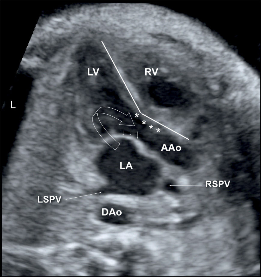
Figure 8.2: Five-chamber view of the fetal heart demonstrating the continuity of the posterior wall of the aorta with the mitral valve (small arrows) and the continuity of the anterior wall of the ascending aorta (AAo) with the ventricular septum (asterisks). The inflow and outflow components of the left ventricle (LV) are seen in one view (open arrow). The right (RSPV) and left (LSPV) superior pulmonary veins enter the posterior wall of the left atrium at this level. RV, right ventricle; LA, left atrium; DAo, descending aorta; L, left.
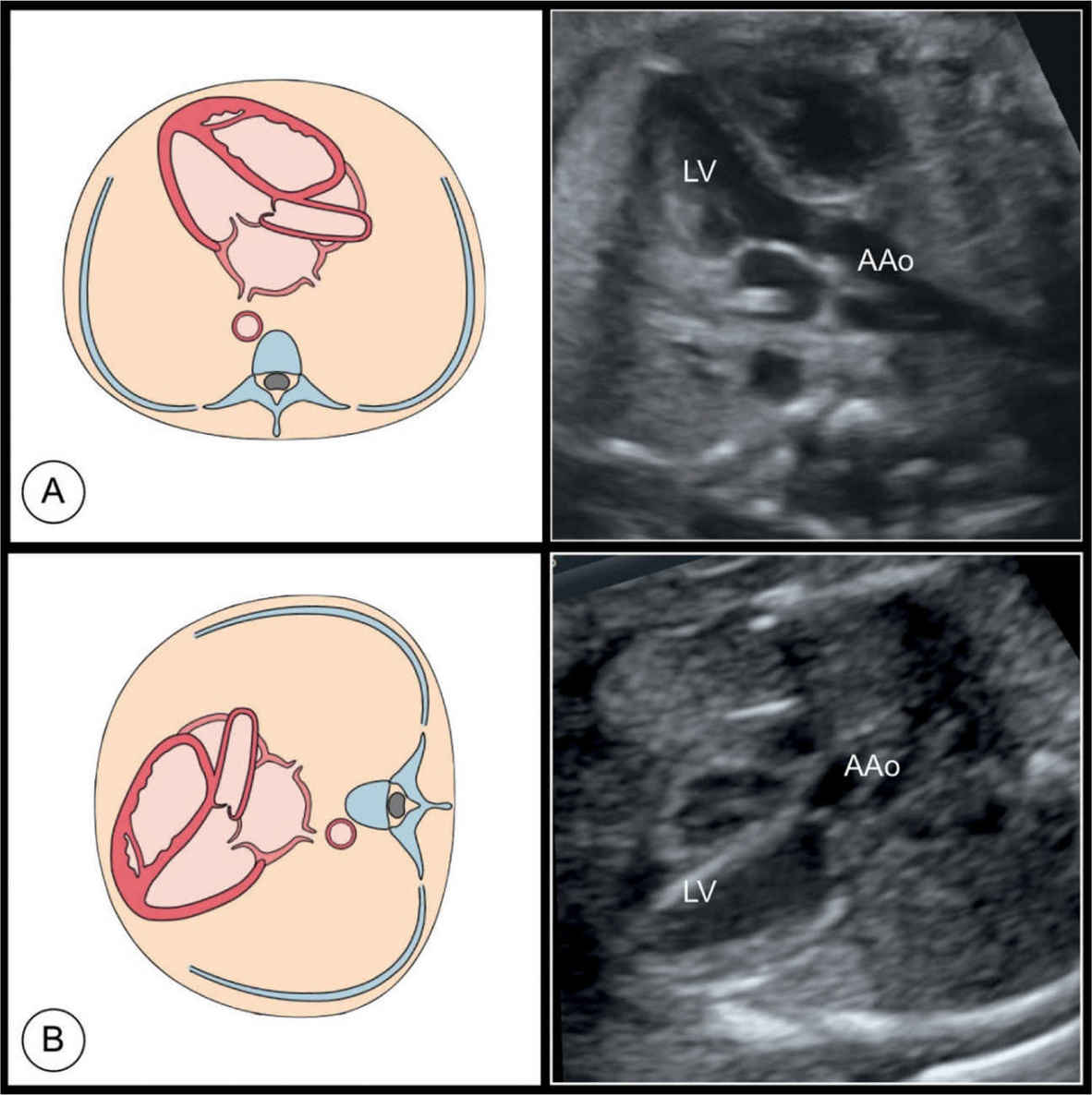
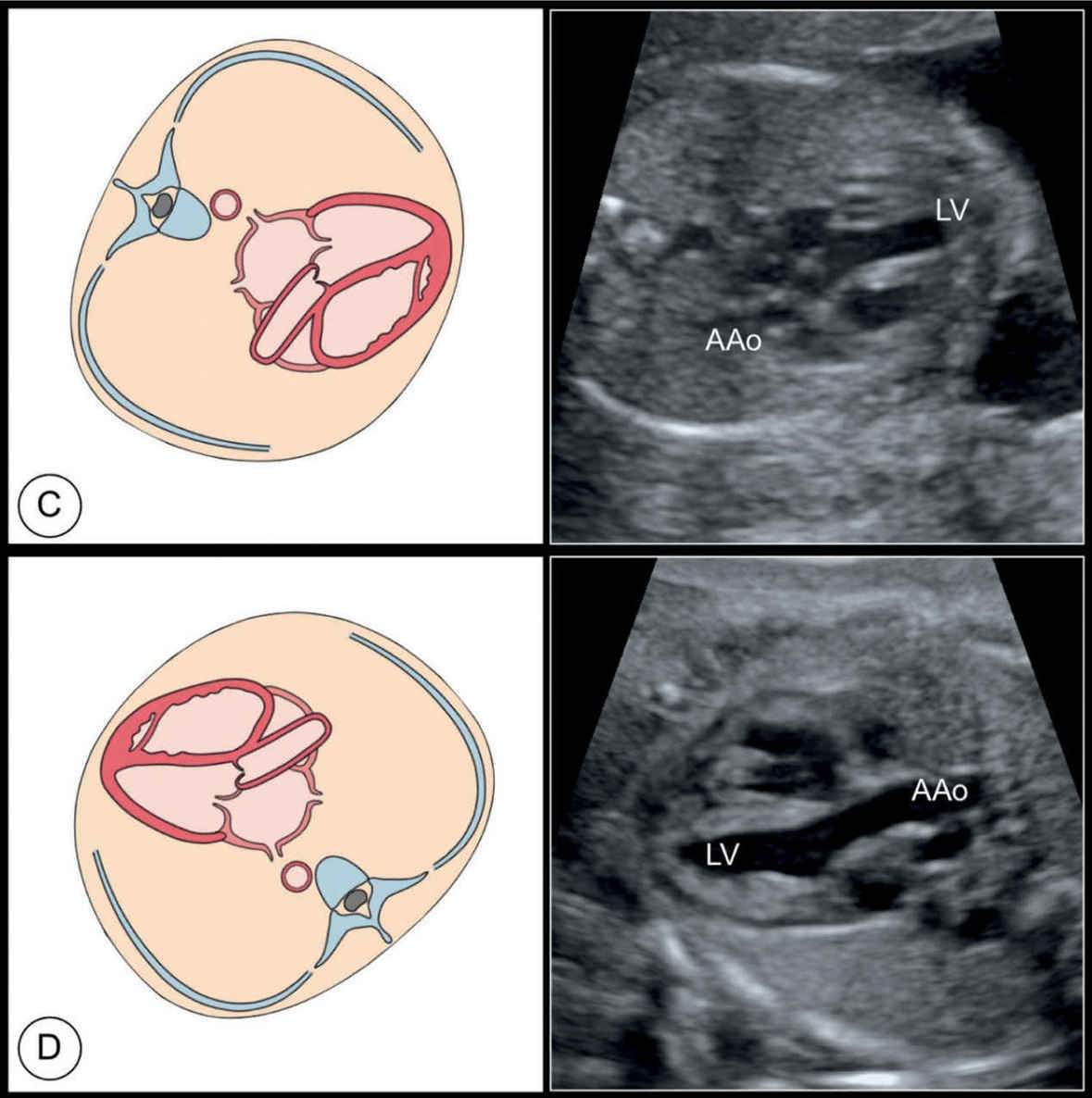
Figure 8.3: Schematic drawings and corresponding ultrasound images of the five-chamber view, obtained in various fetal positions within the uterus. In A, the ultrasound beam enters from the apex of the heart, resulting in an apical five-chamber view, and in B, the ultrasound beam enters from the base of the heart. In C and D, the ultrasound beam is almost perpendicular to the ventricular septum. When the five-chamber view is imaged from a nonapical approach (B, C, and D), shadowing from the ribs may affect visualization. LV, left ventricle; AAo, ascending aorta.
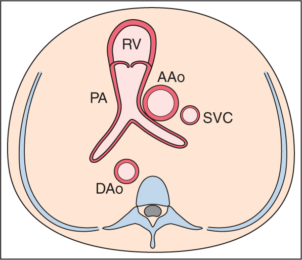
Figure 8.4: Schematic drawing and corresponding ultrasound image of the three-vessel view of the fetal heart demonstrating the pulmonary artery (PA), the ascending aorta (AAo), and the superior vena cava (SVC) in the upper chest arranged in an oblique line (see dashed line) with the PA most anterior, SVC most posterior, and AAo in between. The PA divides into the left (LPA) and right (RPA) pulmonary arteries. The RPA originates at a right angle and runs behind the AAo and the SVC. Eso, esophagus; RB, right bronchus; LB, left bronchus; AzV, azygos vein; DAo, descending aorta; Sp, spine; L, left; R, right.
Stay updated, free articles. Join our Telegram channel

Full access? Get Clinical Tree


