● INTRODUCTION
Three- (3D) and four-dimensional (4D) ultrasound have become an important tool in obstetric imaging in the last decade. Unlike conventional two-dimensional (2D) ultrasound, 3D ultrasound provides a volume of a target anatomic region, which contains an infinite number of 2D planes. The technology of 3D ultrasound is based on advanced mechanical and electronic transducers with the ability to acquire volumes of target organs, through sweeps of elements within the transducers. Rapid computer processors are thus able to display the acquired information within milliseconds. The acquired 3D volume can then be displayed either in a multiplanar format of 2D images or as a spatial volume projecting the external or internal anatomic features of a volume on the screen. Despite these obvious advances afforded by 3D sonography, the acquisition, display, and manipulation of 3D volumes are techniques that require a substantial learning curve. In obstetric sonography, the variable position of the fetus within the uterus further adds to this technical difficulty and limits the clinical applicability of 3D sonography, especially as it involves complex anatomic structures, such as the fetal heart. In this chapter, we will present the basic and advanced principles of 3D ultrasound as it relates to the examination of the fetal heart. Potential applications of 3D sonography in the evaluation of fetal cardiac anomalies are shown in the respective chapters on abnormal hearts later in this book.
● 3D VOLUME ACQUISITION
Optimization of a Volume Acquisition
A prerequisite of a good 3D image or volume is a good 2D image; therefore, the first step in 3D volume acquisition should focus on the optimization of the 2D ultrasound examination. The operator should ensure optimum 2D image quality when scanning the fetal heart by following the steps listed in Table 15.1 as acquisition of a 3D volume initiates from a 2D ultrasound examination. The term reference plane or acquisition plane is used to designate the starting 2D plane for a 3D acquisition.
In the commonly used mechanical 3D transducers, the optimum image quality within a volume is noted in the reference plane and in the planes parallel to the reference plane, whereas the reconstructed orthogonal or oblique planes to the reference plane have a reduced image quality. The reference plane should therefore be chosen based on the anatomic region of interest (ROI) within the heart. The four-chamber plane is best suited as the 3D volume reference plane for the evaluation of the transverse planes of the chest, including the cardiac chambers, origin of great vessels, and the three-vessel-trachea view. On the other hand, optimal evaluation of the aortic, ductal arches, and venous connections is best achieved from a sagittal 3D volume acquisition of the fetal chest. Acquisitions are also best achieved from a near-ventral approach (spine posterior), avoiding shadowing from the ribs and spine.
Three important considerations should be taken into account when acquiring a 3D volume: (a) the size of the ROI (3D box), (b) the angle of acquisition, and (c) the resolution or quality of acquisition.
Steps to Optimize the Two-Dimensional Ultrasound Examination of the Fetal Heart |
• Use the fetal echocardiography presets on the ultrasound machine. • Minimize the depth on the screen. • Narrow the sector width. • Adjust the focal zone(s) to the level of the fetal heart. • Insonate the heart from an angle that avoids shadowing from the fetal skeleton. |
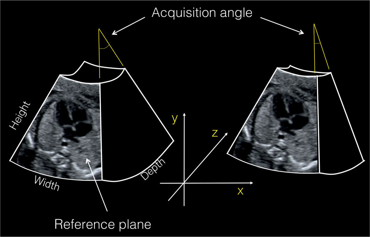
Figure 15.1: Prior to a volume acquisition, the reference plane is chosen by placing a box over the region of interest in 2D ultrasound. The size of the box defines the width (x-axis) and height (y-axis) of a volume. The acquisition angle of a volume corresponds to its depth (z-axis). This figure shows two volume acquisitions with the same width and height but with different depths (acquisition angles). The reference plane (four-chamber view) is located in the middle of the box. It is shown here at the front for better illustration.
1. ROI box: The ROI determines two parameters of a 3D volume—the height and width—corresponding to the x and y axes (Fig. 15.1). It is recommended that the operators use the smallest ROI size that includes all the anatomic components of a target volume. The smallest ROI size that contains all the anatomic components of the fetal heart and its vascular connections will ensure the fastest acquisition while minimizing artifact within the volume.
2. Angle of acquisition: The angle of acquisition is the sweep angle of the elements within the probe and is adjusted by the operator in the 3D preset prior to the 3D volume acquisition. The angle of acquisition refers to the depth of a volume, corresponding to the z-axis (Fig. 15.1). A basic knowledge of the anatomy of the target organ and the type of acquisition is required when choosing an angle for a 3D volume. Current options for the acquisition angle of a volume vary from 10 to 120 degrees based on various equipment manufacturers and specific probes. Spatiotemporal image correlation (STIC) acquisition angles are typically chosen between 20 and 35 degrees. Static 3D acquisition angles are between 35 and 45 degrees, which is generally sufficient for the examination of the fetal chest providing anatomic details extending from the stomach inferiorly to the transverse aortic arch (clavicles) superiorly. Ensuring the smallest angle of acquisition of a 3D volume will enhance the speed of acquisition, reduce artifact, and optimize the quality of the 3D volume.
3. Quality of acquisition: The quality of acquisition refers to the number of planes acquired within a volume (Fig. 15.2). In 3D static acquisition, the quality is referred to as low, medium, or high (Fig. 15.2), whereas in STIC acquisition, the quality of acquisition is influenced by the duration of acquisition: 7.5, 10, 12.5, or 15 seconds (Fig. 15.2). The ROI size, acquisition angle, and quality should be adapted based on the type of 3D volume and the target anatomic region in order to optimize result.
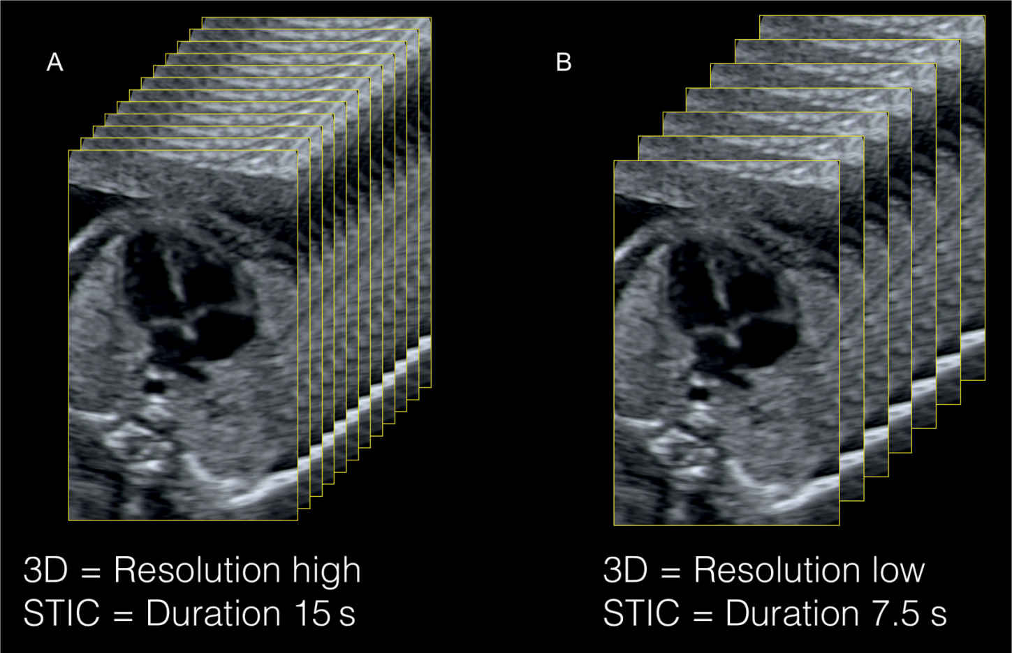
Figure 15.2: 3D volume resolution is dependent on the resolution of the 2D image prior to acquisition and on the number of slices (planes) within the acquisition box. A large number of slices are acquired when resolution is set on high in 3D static acquisitions (A) and when the duration of acquisition is long in spatiotemporal image correlation (STIC) acquisitions (A). The resolution is set on “low” and the duration is short in B, resulting in a smaller number of planes within the volume.
The multiplanar display of a 3D volume provides information on the ROI and the angle of acquisition of the displayed volume (Fig. 15.3). Plane A (left upper) in a multiplanar display corresponds to the reference plane, which is the starting anatomic 2D plane of a 3D volume and thus displays the respective size of the ROI in that volume. Plane B (right upper) in a multiplanar display (Fig. 15.3) is a reconstructed orthogonal plane to plane A and shows the respective angle of acquisition of that volume. In looking at the multiplanar display of a 3D volume, one can gauge the appropriateness of the ROI and the angle of acquisition with regard to the target anatomic organ under study (Fig. 15.3). A proposed nomenclature for the classification of 3D terms was presented by Deng (1). Current options for 3D volume acquisition are hereby presented.
Static 3D
Principle
Static 3D acquisition refers to the acquisition of a 3D volume in a nongated static mode (Fig. 15.4). The acquired volume contains an infinite number of 2D still ultrasound planes with no regard to temporal or spatial motion. Currently, this is the most common mode of volume acquisition in obstetrics and gynecology and is frequently used for 3D evaluation of fetal organs. The four-chamber plane is best used as the reference plane for the static 3D acquisition when cardiac chambers and the origin of great vessels are under study. For the assessment of aortic or pulmonary arches, reference planes in parasagittal orientation are recommended.
Advantages
Advantages of static 3D acquisition of the fetal heart include its speed of acquisition (0.5–2 seconds) and the ease of volume manipulation. Furthermore, static 3D acquisition allows for the possibility to acquire large volumes, both in ROI and angle with minimal artifact. The static 3D acquisition can also be combined with color, power Doppler, or B flow for vascular evaluation of volume content. The authors prefer the use of power Doppler or B flow in static 3D acquisition given its uniform color display (2–4). Motion artifact is minimized when vessel pulsatility is reduced during volume acquisition with power Doppler (2–4).
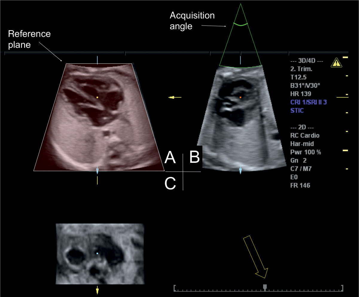
Figure 15.3: Orthogonal display of a spatiotemporal image correlation (STIC) volume acquired at the four-chamber view. The reference plane is depicted in the left upper image (A) with the chosen volume height and width. The acquisition angle 30 degrees is shown in B, in the right upper image. B also provides information on acquisition artifacts (motion). The timeline of the STIC volume is shown in the right lower image (open arrow) and the arrow points to the actual time of the orthogonal display within the cardiac cycle. Moving the cursor over the line allows scrolling through systole and diastole.
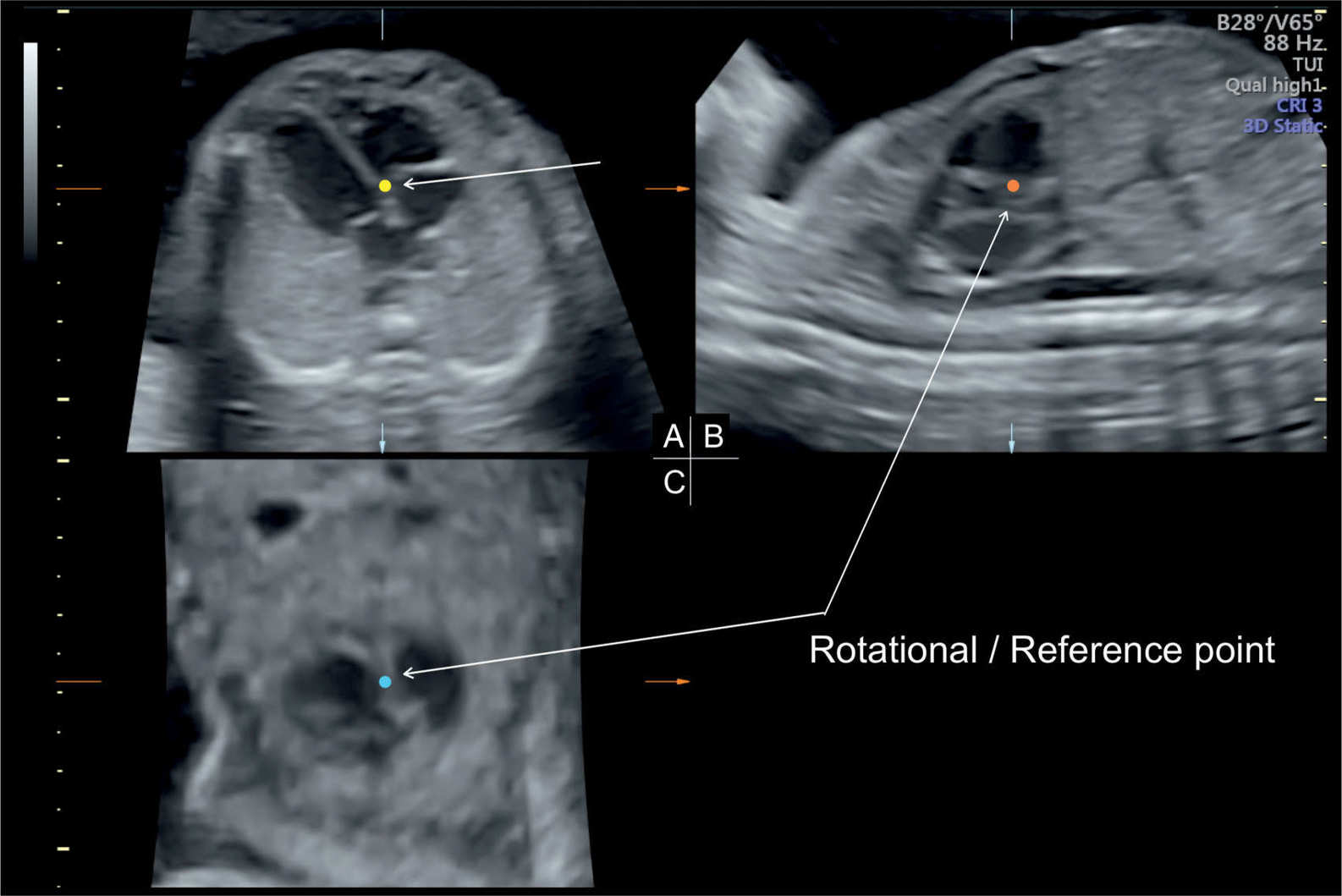
Figure 15.4: Static 3D acquisition of a volume obtained from the transverse fetal chest at the level of the four-chamber view (reference plane—A). B and C are two orthogonal planes to A. The reference (rotational point) is placed on the inlet septum in A (short arrow in A and long arrows in B and C), thus showing the same structure in three orthogonal planes.
Disadvantages
Disadvantages of static 3D acquisition include its inability to assess events related to the cardiac cycle, valve motion in the heart, and myocardial contractility.
Spatiotemporal Image Correlation (STIC)
Principle
STIC acquisition is an indirect, motion-gated, offline mode based on the concept of using tissue excursion concurrent with cardiac motion to extract the temporal information regarding the cardiac cycle. This concept was first suggested in 1996 (5) and adapted to clinical ultrasound several years later (6, 7). The acquisition of a STIC volume occurs over a duration of 7.5 to 15 seconds with an acquisition angle of 15 to 40 degrees. The acquired volume is processed internally, where the systolic peaks are used to calculate the fetal heart rate and the volume images are then rearranged according to their temporal events within the heart cycle, thus creating a cine-like loop of a single cardiac cycle.
Parameters that optimize the acquisition of a STIC volume include a clear 2D reference plane with minimal shadowing by the fetal skeleton; a ROI that is set as narrow as possible, probably just outside the cardiac chambers; an angle of acquisition between 20 and 25 degrees in the second trimester; and a large acquisition time within the 7.5- to 15-second window if allowed by lack of fetal movements. These parameters will enhance the temporal and spatial resolution of the acquired volume and maximize the frame rate (Fig. 15.2).
Advantages
Advantages of STIC volume acquisition include the ability to assess atrial and ventricular wall motion and valve excursion. The 4D information is available within seconds from the volume acquisition, thus facilitating its integration in clinical practice. Once the reference plane is optimized, the STIC acquisition can be easily achieved. STIC acquisition can be obtained from 2D grayscale imaging combined with other imaging modalities, such as color, power, or high-definition flow Doppler and B flow.
Disadvantages
Disadvantages of STIC acquisition include a fairly delayed acquisition time, which can be hampered by fetal movements or maternal breathing movements, thus introducing artifact into the volume.
Real-Time 4D
Principle
A real-time acquisition of a series of 3D volumes is called real-time 4D and can be achieved with a mechanical transducer, but the rotation motor in current technology is a limiting factor in getting a large acquisition angle or good resolution (8). Real-time 4D acquisition of cardiac volumes is, now and in the future, best obtained with matrix array transducers allowing real-time dynamic 4D evaluation. Preliminary experience on matrix transducers is presented at the end of this chapter.
Advantages
Postnatal studies have shown superiority of this approach to conventional 2D ultrasound in the evaluation of congenital heart disease (9–12). Major advantages of real-time 4D acquisitions are that gating of the heart rate is not required and volumes of the beating heart are displayed instantaneously without any transfer or postprocessing of the data. Other advantages include the ability to display on the ultrasound screen instantaneously 2D and real-time 4D volume. Color Doppler can also be added to a real-time 3D acquisition (13). This technology allows for the depiction of the shape, direction, and propagation of color flow jets in 4D for analysis of various congenital heart abnormalities, such as septal defects, valvar stenosis, and regurgitation (13).
Disadvantages
Although this technology holds significant promise for the future, current systems are limited by the small size of the acquired volumes, thus often too small for a complete evaluation of the fetal heart and great vessels, and the high cost of transducers (14).
● VOLUME DISPLAY AS 2D PLANES
The demonstration of the result of a volume acquisition on the screen is called volume display. After a volume acquisition, different options are available for volume display and manipulation. Volume display can be performed by showing either (a) representative 2D images from the volume, termed multiplanar display or multiplanar reconstruction, or (b) external or internal spatial views of the acquired volume, termed volume rendering (see next section).
Single 2D Planes or Multiplanar Orthogonal Display
Principle
Multiplanar mode is based on displaying a 3D volume by three orthogonal 2D planes, conventionally termed planes A, B, and C (Figs. 15.3 and 15.4). Plane A, located in the left upper corner, is the reference plane for the acquisition, and planes B and C are orthogonal planes corresponding to the location of the reference point within the volume (Figs. 15.3 and 15.4). The operator can then display all three planes, two planes, or a single plane on the ultrasound display. Multiplanar display is commonly used for 3D static and STIC acquisitions. STIC displays allow for the ability to play the loop in slow motion or stop at any time (open arrow in Fig. 15.3) for detailed analysis of specific phases of the cardiac cycle. The reference point, which corresponds to the intersection point of the three displayed planes in multiplanar display, can be used for volume manipulation. The authors recommend an easy approach that relies on moving the reference point in planes A or B to the desired anatomic structure within the heart for its display in three orthogonal planes and then performing minor rotations as needed across the x-, y-, or z-axes for full display. Figure 15.4, for example, shows the anatomy of the crux of the heart in three orthogonal planes, which was obtained by placing the reference point on the inlet septum in plane A. Standardization of a 3D volume in multiplanar display, by rotating the spine in plane A to the 6-o’clock position and placing the apex of the heart in the left upper chest, has been previously described in detail (15) (Fig. 15.5 and Table 15.2). Once a 3D-static or a STIC volume obtained at the level of the four-chamber view is standardized as outlined, the diagnostic cardiac planes can be retrieved, as has been described (16). Table 15.3 lists the spatial relationship of standard diagnostic cardiac planes in the fetal heart to the four-chamber-view plane in the second trimester of pregnancy (16).
Advantages
Advantages of multiplanar display include familiarity with the displayed 2D planes, the relative ease of manipulation of the volume given the acquaintance with the displayed 2D anatomy, and the ability to view cardiac abnormalities from three orthogonal views simultaneously. By scrolling through an acquired STIC volume, the operator not only can sequentially display many diagnostic planes, such as the abdominal plane and four-chamber, five-chamber, and three-vessel-trachea views (Fig. 15.6 D–G), but also can review planes within a specific time within the cardiac cycle (Fig. 15.6B,C). Methods for examination of the fetal outflow tracts in 3D static and STIC volumes have been described, including the “spin” technique, which involves rotation along the x and y axes (17). The potential of color Doppler STIC volumes for the evaluation of normal and abnormal hearts was studied in a prospective design in experienced hands (18). Successful acquisition was possible in all cases and the display of the three transverse planes (four-chamber view, five-chamber view, and three-vessel-trachea view) was possible in 31 of 35 normal hearts and in 24 of 27 abnormal hearts (18).
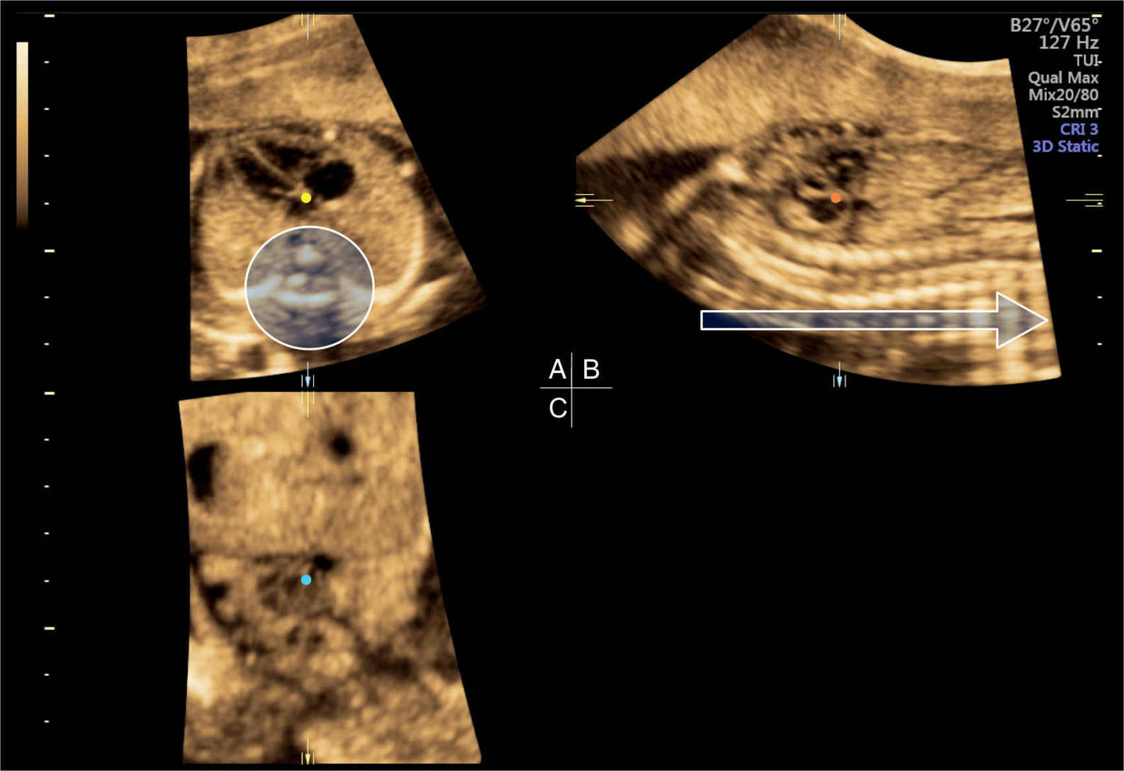
Figure 15.5: Static 3D acquisition of a volume obtained at the level of the four-chamber view (reference plane—A). Standardization of a 3D volume of the fetal chest is achieved by rotating A along the z-axis to place the spine at the 6-o’clock position (circle) and the apex of the heart in the left upper quadrant. Further standardization involves rotating B and C along the z-axis to align the spine horizontally (open arrow) and vertically in B and C, respectively, and placing the rotational/reference point in the crux of the heart in A (yellow dot). The spine in C is not seen as the reference dot is placed at the inlet of the heart. See text and Table 15.2 for further details.
Standardization of Three-Dimensional Volumes of the Fetal Chest (Cephalic Presentationsa) |
VOLUME ACQUISITION • Reference plane: Obtain an axial view of the chest at level of the four-chamber view. Ensure that you have one full rib on each side. • Acquisition box: Open the acquisition box wide enough to ensure that the fetal chest is contained within the box. The box boundaries should be placed just outside the fetal skin. • Acquisition angle: Use an acquisition angle that is wide enough to include the stomach inferiorly and the lower neck superiorly. |
VOLUME DISPLAY 1. Rotate image in plane A (four-chamber view) along the z-axis until the spine is at 6-o’clock position and the apex of the heart is in the left upper chest. 2. Move the reference point in plane A to the spine (body of vertebra). This will bring a longitudinal view of the spine in planes B and C. 3. Rotate image in plane C (coronal view) along the z-axis until the section of the midthoracic spine is aligned vertically. 4. Rotate image in plane B (sagittal view) along the z-axis until the section of the midthoracic spine (posterior to the heart) is aligned horizontally. 5. Place the reference point in plane A at the crux of the heart, at the level of the insertion of the medial leaflet of the tricuspid valve into the septum. |
aFor breech presentations, start by rotating the 3D volumes 180 degrees along the y-axis, and then follow the steps above.
From Abuhamad A. Standardization of 3-dimensional volumes in obstetric sonography: a required step for training and automation. J Ultrasound Med. 2005;24:397–401, with permission.
Cardiac plane | Spatial relationship to 4CV | TUI image-to-image distance (mm)a |
1 | Parallel shift: –3.84 mm | 0.56 |
2 | Parallel shift: –9.00 mm | 1 |
3 | Parallel shift: +14.0 mm | 2 |
aTUI output was set at seven images for each diagnostic cardiac plane.
Cardiac 1, left ventricular outflow tract; cardiac 2, right ventricular outflow tract; cardiac 3, abdominal circumference.
From Abuhamad A, Falkensammer P, Reichartseder F, et al. Automated retrieval of standard diagnostic fetal cardiac planes in the second trimester of pregnancy: a prospective evaluation of software. Ultrasound Obstet Gynecol. 2008;31:30–36, with permission.
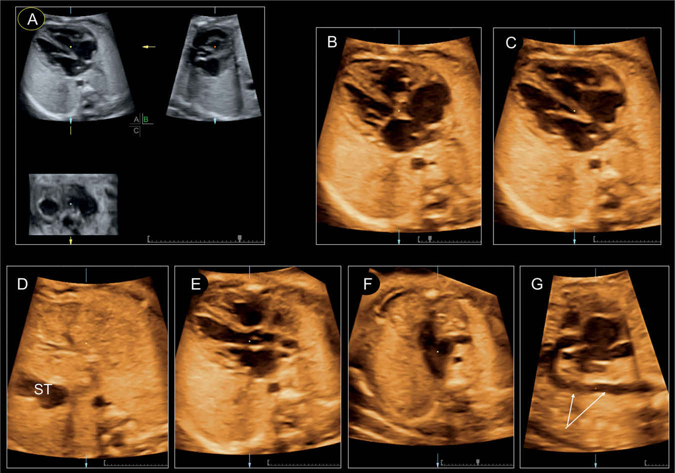
Figure 15.6: Manipulation of a spatiotemporal image correlation (STIC) volume. The original STIC data set is shown in an orthogonal plane display in A. The four-chamber plane as a “single plane” is demonstrated in systole (B) with closed atrioventricular valves and in diastole (C) with opened valves. Scrolling through the volume demonstrates the upper abdomen with the stomach (ST) (D), the slightly oblique five-chamber view (E), the three-vessel-trachea view in the upper thorax (F), and a reconstructed longitudinal plane (G) of the aortic arch. Reconstructed planes are generally of lower quality; note the presence of motion artifact in G on the descending aorta (arrows in G).
Disadvantages
Disadvantages of 2D plane display are mainly related to the reconstructed planes in comparison to a live examination. Artifacts during acquisition may produce artifacts of the 2D reconstructed plane with erroneous information. We recommend acquiring several volumes of the fetal heart in order to improve the accuracy of the offline analysis.
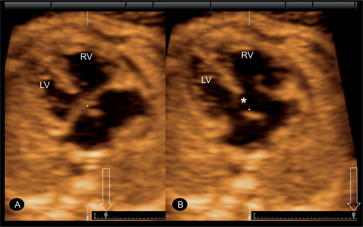
Figure 15.7: Spatiotemporal image correlation (STIC) volume in a fetus with an atrioventricular septal defect. In A, the defect is not clearly demonstrated as the valve leaflets are closed. By scrolling through the cursor (open arrow), the interventricular septal defect is clearly demonstrated (asterisk) in B when the valve leaflets are open. LV, left ventricle; RV, right ventricle.
Application in Fetal Cardiac Anomalies
The 2D plane display can be applied in the evaluation of all cardiac anomalies as it can mimic a real-time examination of the fetal heart when the examiner scrolls through the volume in slow motion (Fig. 15.6). This application can be of help in the detection of atrioventricular septal defect (Fig. 15.7), when the plane at the level of the crux of the heart is carefully observed during systole and diastole (Fig. 15.7A,B). The reference point at the intersection of the three orthogonal planes can be used to confirm the presence of a ventricular septal defect demonstrated then in all three planes. The reference point can also demonstrate the parallel orientation of the great arteries in transposition cases (17). An optimal view of the aortic arch can be reconstructed from a parasagittal acquisition of the fetal chest to demonstrate the continuity and the normal size of the aortic arch (Fig. 15.6).
Multiplanar Tomographic Ultrasound Imaging
Principle
Tomographic ultrasound imaging (TUI), or multislice analysis, is a modification to multiplanar imaging, where numerous parallel 2D planes are simultaneously displayed, giving a sequential anatomic view of a region within the acquired volume (Fig. 15.8). The number of displayed planes, the interplane distance, and the thickness of the anatomic region can be manipulated (compare Figs. 15.8 and 15.9). The exact position of each plane within the target anatomic region is seen in the upper left plane of the TUI display (Fig. 15.8A).
Advantages
Tomographic ultrasound display resembles the output of computed tomography and magnetic resonance imaging and thus has the advantage of displaying multiple planes in longitudinal, transverse, and coronal orientation, providing a comprehensive picture of cardiac anatomy. Most fetal cardiac anomalies affect different segments of the heart, and a comprehensive examination should include the assessment of different planes, which can be demonstrated in one picture when displayed in TUI mode. The advantage of TUI in the evaluation of cardiac anomalies was analyzed in 103 confirmed cases of congenital heart malformation (19). A mean interslice distance of 2.7 mm (standard deviation [SD], 0.3) at 19 to 23 gestational weeks and 4.0 mm (SD, 0.4) at 30 to 33 weeks allowed a complete sequential analysis in all cases (19). Algorithms for the automatic display of diagnostic cardiac planes out of a 3D static or STIC volume have been described following an initial standardization in plane A (20). This technology of automated sonography has the potential of standardizing and simplifying the ultrasound examination of the fetal heart by lessening the operator dependency on the conventional 2D ultrasound modality. TUI is a significant component of automated sonography as it controls for inherent variability in fetal cardiac anatomy (cardiac axis, cardiac position in chest, size of chest) by providing multiple planes for review (Figs. 15.8 and 15.9). In a study evaluating the automated software on STIC volumes of fetuses with transposition of great arteries, ventricular arterial connection anomaly was shown in all fetuses (21) (see section Automated Multiplanar Imaging).
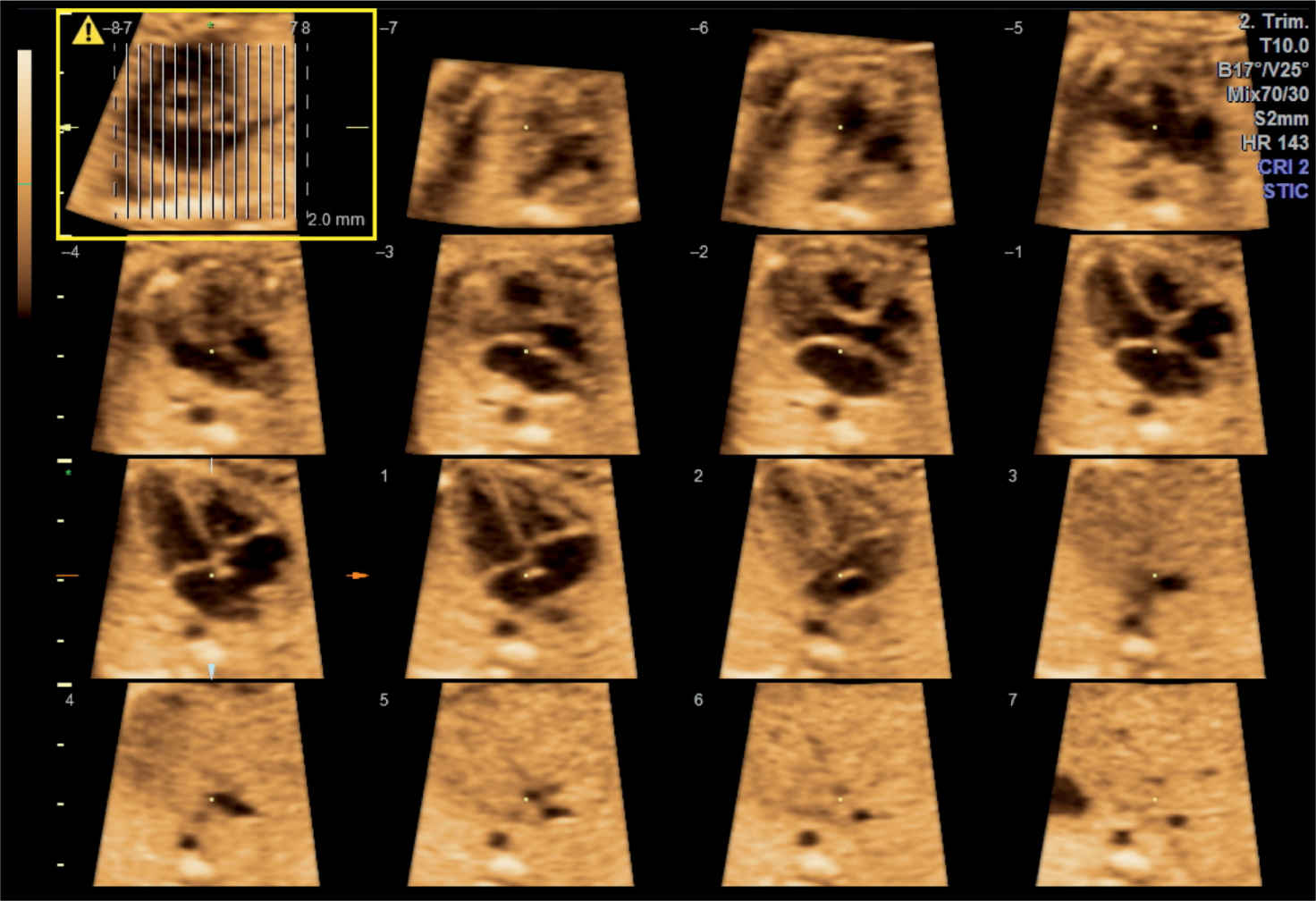
Figure 15.8: Tomographic ultrasound imaging of a spatiotemporal image correlation (STIC) volume of the fetal heart in gray scale. In the upper left image, the orientation plane (A) is seen (highlighted in yellow) with the parallel vertical lines referring to the planes shown in the display (–7 to +7). The examiner chooses the interplane distance and the total number of planes.
Stay updated, free articles. Join our Telegram channel

Full access? Get Clinical Tree


