Spinal Examination and Specific Spinal and Pelvic Adjustments


Spinal Examination and Specific Spinal and Pelvic Adjustments


Claudia A. Anrig


The focus of this chapter is on the analysis and manual adjustive correction of subluxations affecting the spinal column and pelvis. It is the author’s intent to provide as much detail as possible about the specific application of examination strategies as well as techniques that emphasize the return to normal motion segment and nervous system function.

Very little research exists on the efficacy of the various adjustive techniques described in this chapter. This is largely because of the dearth of scientific information in general with respect to the various health professions (1) rather than any state of affairs unique to the chiropractic profession. In the interim, however, patients must be treated because of the unique ethical contract between doctor and patient, regardless of the state of science. One is reminded that the individual patient who presents to a doctor was never in a clinical trial, and so it is extremely difficult to predict outcomes for this individual patient. The art of being a doctor is to apply methods that seem to have the best chance for optimizing function and hold the least possibility of attendant risk. The art of chiropractic includes an adjustment that moves the segment toward normal with the least trauma imparted to the associated soft tissue elements. All adjustments, especially those applied to the pediatric population, require a high level of skill. Non-specific introduction of forces into the delicate spine because of an ignorance of biomechanics cannot be tolerated.

Insofar as many clinical applications are considered, the practitioner should base their approach on an understanding of normal biomechanics and the mechanisms of trauma coupled with a reasoned approach that attempts to not only “do no harm,” but that also moves the motion segment toward normal, which is generally opposite the forces of injury. All of the adjustments presented in this chapter are extremely detailed in their presentation and should be based on the clinical circumstances of the individual patient. The fact that the pediatric spine can withstand many loads the child is subjected to throughout life should not lead to the naive assumption that a doctor can do no harm. Moreover, the application of adjustment techniques in the adult cannot be applied to the infant’s or toddler’s spine. Size differences in the anatomic elements as well as the unique flexibility differences of the spinal column at different ages necessitate a specific approach.

The more salient adjustive procedures currently being used in the chiropractic profession are discussed. The treatise is not all-encompassing, but should serve as a basis from which the clinician can formulate a cogent analytical and adjustive plan. Certain techniques that do not move the motion segment three-dimensionally toward center, involve long lever arm vectors, or otherwise compromise delicate neurological or vascular tissues (2) are specifically contraindicated and presented as such. The hope is that clinicians who are unfamiliar with adjustive care of children, or those who have been applying techniques in a nonspecific fashion to pediatric populations, will begin to refocus their efforts toward the correction of the subluxation in as specific a manner as possible and with the least likelihood of doing harm. In this way the application of chiropractic techniques can truly reach our youngest with the greatest potential for minimizing the deleterious neurological effects of spinal trauma.


MECHANISM OF INJURY

A description of micro or macro trauma should be always considered as a part of the assessment process. The history and current presentation of the child may assist in understanding the cause of trauma to the
pediatric spine and the vertebral subluxation complex (VSC; i.e., positional dyskinesia).


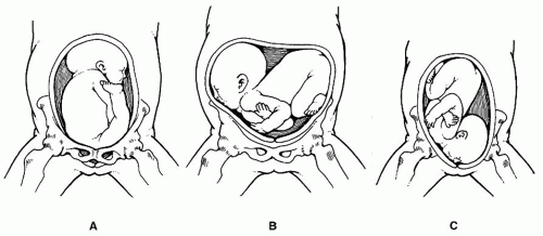
FIGURE 5-1 A: Breech presentation. Notice the position of the legs. Modified from Graham JM. Smith’s recognizable patterns of human deformation (2nd ed). Philadelphia, PA: W.B. Saunders Co., 1988; p. 86. B: Transverse lie presentation. Modified from Graham JM. Smith’s recognizable patterns of human deformation (2nd ed). Philadelphia, PA: W.B. Saunders Co., 1988; p. 95. C: Face presentation. Modified from Graham JM. Smith’s recognizable patterns of human deformation (2nd ed). Philadelphia, PA: W.B. Saunders Co., 1988; p. 96.

In-utero constraint (3,4,5), which includes breech, transverse lie, brow and facial presentations may lead to repetitive microtrauma to the spine (Fig. 5-1A-C). The upper cervical region, specifically the occipital condyle, should be suspected as a possible positional dyskinesia (i.e., anterior-superior [AS] or posterior-superior [PS] listing) as a result of in-utero constraint. Other complications to consider are the cervical and upper thoracic spine in an extended hyperlordotic presentation (e.g., facial, transverse) or the lumbosacral spine in a flexion position (e.g., breech).

The birth process is well documented as a potential source of trauma to the spine and spinal cord (4,6,7,8,9,10). The most common insult to the spine is forceful tractioning while the cervical spine is in hyperextension. Other forms of trauma are longitudinal traction with rotation and flexion or excessive lateral flexion (5). The use of any long lever device (e.g., vacuum extractor, forceps) as seen in Figures 5-2 and 5-3 or the introduction of invasive techniques (e.g., Caesarean section, obstetrician hand dominance) should be documented as a possible neonate trauma.

The handling of newborns and infants may cause microtrauma to the spine. Diapering techniques (Fig. 5-4) and lifting from a crib or car seat may place a strain on the spine with the undeveloped supporting muscles. Baby walkers (which are outlawed in some countries because of safety hazards) and jumpers place undue stress to the lower limbs and lumbopelvic region. An unsupported neck and upper thoracic spine while the caretaker is carrying the newborn may cause repetitive microflexion and extension spinal trauma.

Falls are not uncommon with young children. A National Safety Council (11) noted that 47.5% infants were discovered to have fallen from a high place during their first year of life. The toddler is prone to repetitive compression forces on the buttocks when learning the skill of walking. The forward uncoordinated gait of the toddler often results in frontal skull strikes (e.g., into furniture). This mechanism of injury may
result in extension or flexion trauma to the occiput and cervical and upper thoracic regions.


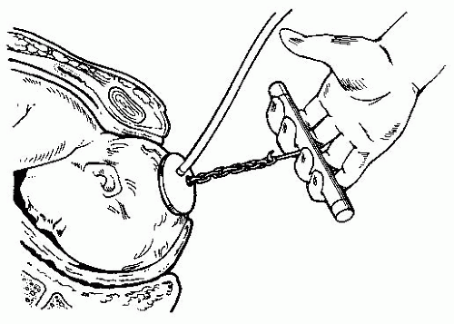
FIGURE 5-2 Bird’s modification of Malmstrom’s vacuum extractor method. Modified from Pernoll ML, Benson RC. Current obstetric and gynecologic diagnosis and treatment. 6th ed. Norwalk, CT: Appleton & Lange, 1987; p. 496.


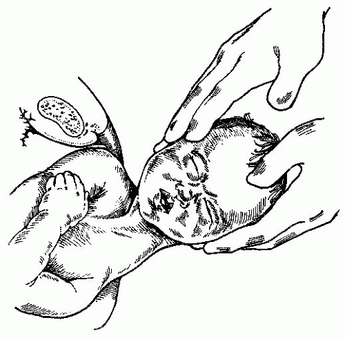
FIGURE 5-3 Delivery with upward traction applied to the head to deliver a posterior shoulder over the perineum. Modified from Wilson JR, Beecham CT, Forman I, Carrington ER (eds). Obstetrics and Gynecology. St. Louis, MO: CV Mosby, 1958; p. 336.

The preschooler is no exception to falls (e.g., biking, playing, skating). Often, sports activities are introduced into their lives (e.g., soccer, gymnastics), which bring asymmetrical forces into the developing spine.


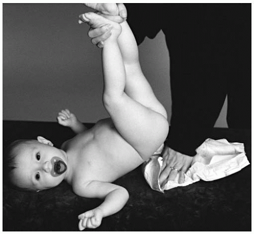
FIGURE 5-4 Certain diapering techniques may place unnecessary stress on the spine.

Other spinal considerations for the child include sleep positions that are developed. Stomach sleeping habits are not suggested in the newborn/infant because of the possible link to sudden infant death syndrome (12). In addition, this position is not recommended for any age because of the biomechanical stress (e.g., rotation, favoritism to one side) at the cervical spine.

The school-age child (5 to 18 years old) is prone to more traumas on the school campus (7), including organized and unorganized sports. Playschool equipment (7,13) is a frequent site of trauma. Bicycling, skateboarding, roller-skating, horseback riding, use of water slides, and diving (14,15) are a few common activities of the young. Hyperflexion and hyperextension of the neck or compression of the buttocks or head can cause either spine or spinal cord injury (see Chapters 20 and 23).

Microtrauma may be seen in the form of postural insult caused by behavioral habits. Poor sitting habits (e.g., slumping, slouching) may contribute to stresses on the spine (Fig. 5-5). Chairs in classrooms are often not ergonomically designed. Backpacks that are incorrectly carried on one shoulder or are too heavy may be an asymmetrical strain on the spine (Fig. 5-6).


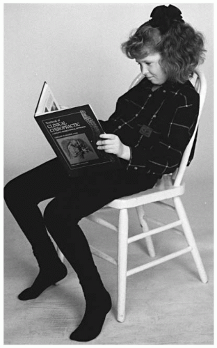
FIGURE 5-5 Poor design and use of school chairs places repetitive stress on the developing spine.


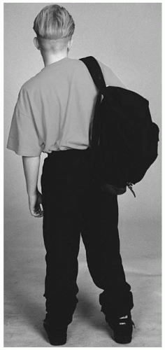
FIGURE 5-6 Asymmetrical usage of the backpack places repetitive stress on the musculoskeletal system.

The leading cause of accidental death in children is vehicle related (7). Chapters 20 and 23 discuss in more detail the mechanisms of injury to the pediatric spine and nervous system.

Child abuse (see Chapter 16) is more common than one may suspect. Physical abuse often includes the forceful striking or shaking of the victim. Infants are not immune when violent shaking of the head occurs (14,16,17). Spinal cord trauma can result.


MANAGEMENT

Recording the history of the child can assist the practitioner in understanding not only the mechanism of injury but also the need for ongoing evaluation of the pediatric spine. The elimination of micro or macro trauma to the child is highly unlikely. Parents and children should be instructed and educated about how to diminish spinal injury.

The frequency of care should be individually assessed. The VSC in its earliest stages may not manifest as a clinically symptomatic disorder (18). Objective findings, not necessarily a symptomatic picture alone, should be the criteria for its identification. The rendering of spinal adjustments in the young may be one of the most effective forms of contributing to the prevention of spinal dysfunction and other health disorders. Longitudinal studies should be conducted to determine the effectiveness of chiropractic care as part of a prevention program.

During the consultation and after the clinical assessment of the patient, the doctor should thoroughly explain the objective findings. It is during this time that the doctor can inform the parents of three general phases of chiropractic care. Relief care, which is the rendering of care until relief or stabilization of the condition is achieved, varies from several weeks to several months. Visits are usually more frequent in the beginning and decrease as objective findings diminish. Corrective/rehabilitative care is the delivery of care to alter more permanently the biomechanical structure of the spine. This type of care would be required, for example, when a hypolordosis or kyphosis of the cervical spine or scoliosis is present. Frequency of visits varies depending on many factors: objective findings for biomechanical changes, age, and lifestyle habits.

The third phase of care has been called by the following names: prevention and wellness. This program is the rendering of spinal adjustments when subluxations are present to allow the developing spine and its influence on the nervous system to have optimal function during the course of the child’s developmental process. This program is similar to the preventive approach of dentistry. The evaluation of the spine will be generally more frequent than in dentistry because of the ongoing stresses and vulnerability of the spine. The frequency rate may be greater if the child is going through a stage of increasing repetitive falls or stresses to the spine. The purpose of the visits are to evaluate the spine and to adjust if objective findings are present. It is negligent for the doctor to space out the visits when objective findings and the child’s lifestyle warrant more frequent evaluation. At the other extreme, it is suspect to justify the necessity of high-frequency/long-term (e.g., daily visits for months) care by the practitioner.

An outline for evaluating the spine must be determined by many factors, including age, environment, developmental stages, and activities. The purpose of a visit is to evaluate objectively for the need to adjust. If objective findings are not present, the doctor reschedules for the next visit. The neonate should be evaluated shortly after birth (within 48 hours). The newborn/infant should be examined on a regular schedule between 2 and 6 weeks unless a specific trauma results, in which case the child should be seen immediately. The more active toddler and preschooler may need an evaluation between 2 to 4 weeks because of their repetitive microtraumas.


For the less active pre-adolescent and adolescent patient, the frequency of care may vary from 2 to 6 weeks. The more active patient may require a closer evaluation visit frequency. This recommendation can vary for numerous reasons. If the patient is under care for a correction of a biomechanical disorder (e.g., scoliosis) or for an injury (e.g., automobile accident, sports) the frequency and length of care will be increased.


SPECIFIC CONTACT, SHORT LEVER ARM ADJUSTIVE TECHNIQUES

The method of delivery that is emphasized is specific short lever arm adjustments (Fig. 5-7). The use of a listing system (see Chapter 4) allows for a systematic reference to the positional dyskinesia of the subluxated segment to be adjusted. The adjustment specifically directs a three-dimensional force away from the direction of misalignment. The advantage of specific adjusting allows for the protection of the supporting ligamentous elements. A short lever-specific contact on the subluxated segment protects normal functional spinal units. The practitioner can protect the normal segments from introduction of unnecessary force during the adjustive thrust by the considerations of pre-loading and end-range positions described below.

A specific adjusting approach includes patient management. Rather than randomly introducing multiple forces into spinal segments, the doctor limits the number of segments to be adjusted through a prior spinal evaluation. The rationale of limiting the segments to be adjusted allows for the practitioner to objectively assess the results.


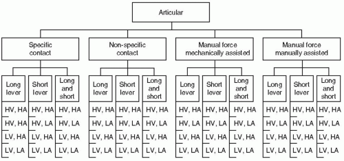
FIGURE 5-7 Articular procedure descriptions. H, high; L, low; V, velocity; A, amplitude. Modified from Bartol KM. A model for the categorization of chiropractic treatment procedures. Chiropr Tech 1991;3:79.


PRIMUM NON NOCERE

“Above all, do no harm” should be the primary consideration of all health professionals. This principle should be applied during the examination as well as the adjustment. Knowledge of the relative positions of the vertebrae will prevent further joint insult. The adjustment should avoid introducing unnecessary forces into the neural elements, cartilage, disc, and articular ligaments. No adjustment should ever be performed without evidence of a relative decrease in mobility at that articulation.


HYPOMOBILITY VERSUS HYPERMOBILITY

One major component of the VSC is kinesiopathology. This begins with hypomobility of the vertebral segment. Commonly associated with hypomobility is the compensation of hypermobility within the same region of the spine (19). Symptoms related to the hypermobile region are not uncommon. Careful evaluation of the spine decreases the possibility of adjusting a hypermobile segment (12). Compensation in spinal regions has been brought forth by numerous individuals (e.g., Gonstead, Jirout, Gillet). Static and motion palpation can assist in detecting hypermobility with associated edema and
tenderness. Introducing forces into a hypermobile or normally functioning joint is contraindicated.


LONG LEVER AND NON-SPECIFIC ADJUSTMENTS

Long lever contacts or general mobilization of a spinal region is not beneficial to the developing spine. The elastic properties of the spine and spinal cord dictate the elimination (or minimizing) of vectors that would introduce unnecessary and possibly harmful forces into the spine. Patient placement or the doctor’s set-up should avoid the following forces and bending movements: longitudinal traction, extension, rotation, flexion, and lateral flexion.

Long lever techniques should not be performed on the pediatric spine. These adjusting procedures traditionally approach the spine with less specificity and the introduction of possibly harmful long lever forces. Examples of non-specific cervical techniques are supine or prone rotary breaks (Fig. 5-8), seated rotary breaks (Fig. 5-9), or hyperlateral flexion and rotation (Fig. 5-10). The thoracic spine receives unnecessary rotation with the upper thoracic thumb move (Fig. 5-11) or non-specific mobilization, as seen in the “anteriority” set-up (Fig. 5-12A-C). The lumbar spine
is susceptible to the introduction of rotation by poor upper torso stabilization (Fig. 5-13A,B) and excessive leaning or “kicking down” on the superior bent leg. Several general mobilization techniques are dangling or holding infants in the air either by their feet, under the axilla, or with hands wrapped around the thoracic spine, followed by a random snap, shake, or whip to the spine (Fig. 5-14).


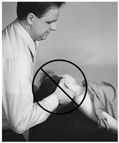
FIGURE 5-8 To pre-load the joint for the supine rotary break, it is necessary to position the cervical spine in extension and Y-axis rotation.


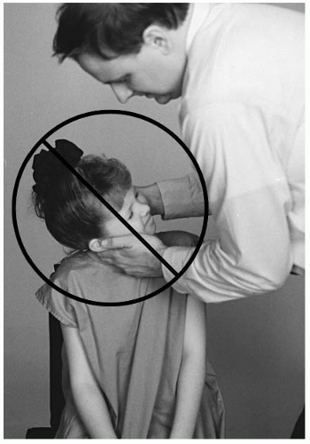
FIGURE 5-9 Long lever techniques are contraindicated for the pediatric spine.


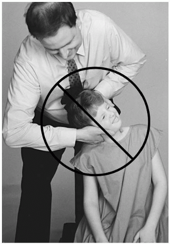
FIGURE 5-10 Lateral flexion with rotation places undue stress on the spinal elements.


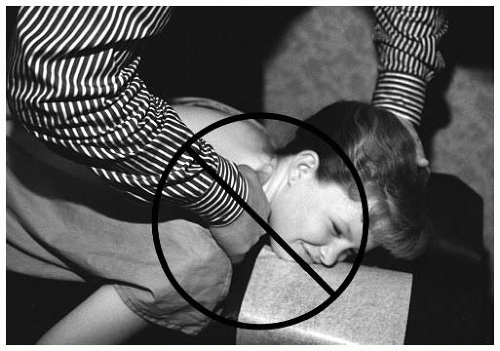
FIGURE 5-11 The diversified thumb move introduces unnecessary Y-axis rotation.


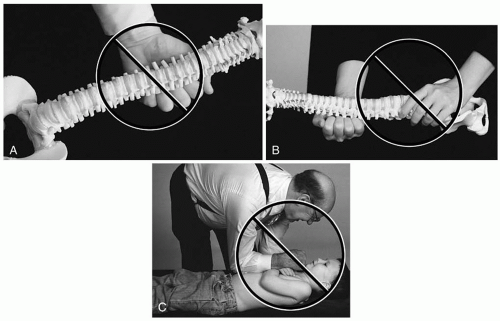
FIGURE 5-12 A-C: The anterior thoracic adjustment is a non-specific manipulation for the developing spine. The doctor overcontacts the spine and ribs.

Other contraindications to the adjustment are joint instability, destruction or fracture of the neural arch or segmental contact point (e.g., spinous process), and infection of the contact vertebra.


PATIENT AND DOCTOR PLACEMENT

The patient should be placed in a neutral or near neutral position. Prone on a parent’s lap, pelvic or hi-lo table, seated on a chair, or side posture on the pelvic bench provide the neutral set-up. The doctor should stand in a position close to the patient and at an angle that allows for an optimal line of correction with the contact arm. The doctor should avoid placing the contact arm at an angle that would introduce a counter-productive force (e.g., rotation, lateral flexion).


CONTACT AND STABILIZATION

The placement of the doctor’s contact and stabilization hand is an important consideration. The anatomic size of the patient’s segmental contact point (e.g., spinous, transverse, mamillary process) is part of the clinical assessment before the adjustment. Traditional contact
hand positions (e.g., pisiform, thenar eminence, the length of the digit) may be too large and contraindicated for the smaller pediatric spine. The possibility of overlapping several spinal segments, or on to the ribs in the case of a thoracic contact, is likely with traditional contact hand set-ups (Fig. 5-15).


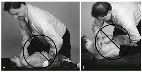
FIGURE 5-13 A,B: Torso rotation introduces unnecessary forces into multiple spinal units.

The distal end of a digit, specifically the fifth digit, is ideal for the newborn, infant, and toddler spine. The second digit is a choice for the larger contact processes. The pre-adolescent and adolescent may be contacted with a traditional hand set-up. The supporting hand is used to stabilize the spinal segments above and below the contact vertebra or the crossed arms of the child in front of the chest in the side posture position.


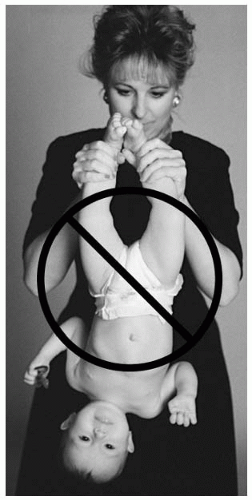
FIGURE 5-14 Dangling the infant by the ankles to perform a whipping movement of the spine is contraindicated.


SPINAL ADJUSTMENT

Spinal adjustments are accomplished in two phases (20): the acceleration-deceleration process. The patient receives force during the adjustment from the mass of the doctor during deceleration after impact with the patient (21). The thrust, or acceleration phase, is the result of the doctor’s mass and acceleration of the adjustive thrust, which yields the force initiated by the doctor to reach the necessary impact velocity. During the deceleration phase, the doctor’s mass is multiplied
by the deceleration, which results in the actual adjustive force produced by the doctor-patient impact.


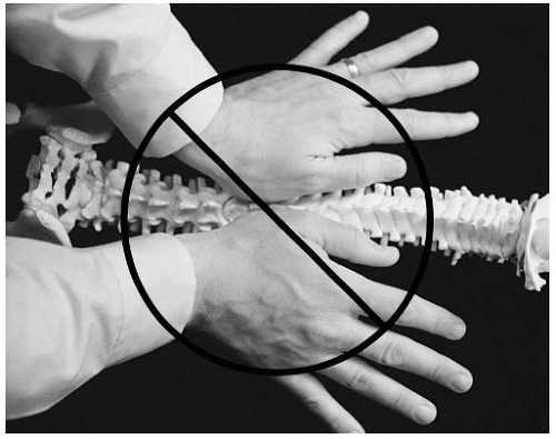
FIGURE 5-15 Overlapping several spinal segments may occur with a traditional hand contact.

Other factors also contribute to the overall force the patient receives. The doctor’s contact (e.g., pisiform, distal end of a digit) and the segmental contact point on the patient (e.g., mamillary, transverse process) contribute to the amount of force the patient receives. The presence of more soft tissue (e.g., infant brown fat) results in a greater dissipation of forces and a slower transference of energy (22,23) from the doctor to the patient. To minimize the force dampening effect, specific doctor and patient contact points are preferred.

Spine flexibility of the patient must also be considered. Tissue pull and pre-load tension are essential in the set-up procedure for the young spine. When performing a tissue pull (usually in the direction of the thrust), careful attention is paid to patient comfort. Pre-load tension is generally greater in the pediatric spine because of its flexibility. Pre-load is often greater than in a more rigid adult spine. The purpose of pre-loading is to prevent the need for extra force to reach the end range of motion of the segment. High-acceleration thrusts will provide the force necessary to overcome the moment of inertia of the functional spinal unit. The deceleration phase is followed by a “hold” for 1 to 2 seconds (Figs. 5-16 and 5-17) (24). The doctor should gradually release the contact after the “hold.” The purpose of “holding” after the adjustment is to affect the viscoelastic tissues with a more lengthy time component, thereby increasing the effectiveness of the adjustment on the elements. When preparing for the adjustment the doctor should interpret the “feel” of the patient’s tolerances and adjustment requirements. Two patients may present with similar morphological characteristics but require vastly different pre-loading, set-up time, relaxation, and force needed to accomplish the adjustment. The doctor’s evaluation and clinical experience will allow for adaptability to individual patient needs.


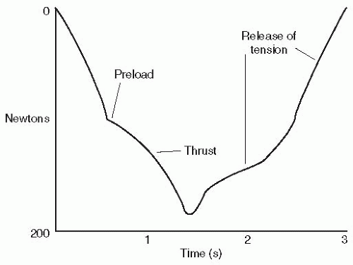
FIGURE 5-16 A qualitative graph of a set-hold type of adjustment thrust.


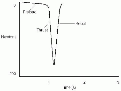
FIGURE 5-17 A qualitative graph of a toggle-recoil type of adjustment thrust.

The amount of force necessary to re-establish normal joint function varies with each patient. The patient’s morphology and the doctor’s adjustive skills are two important considerations. Studies on the peak force for the adjustment of the adult spine have been conducted (25,26,27,28,29,30,31). Although studies in children are lacking (and are warranted), some correlation may be drawn from the adult studies. Less force is necessary in the newborn/infant than the toddler, and less force is required for the toddler than the adolescent. The cervical spine requires more acceleration for the adjustment.

The audible cracking sound as a result of an adjustment is caused by coaptation of articular gases in the synovial joints (32). After the coaptation of a joint there is a refractory period (33). During the refractory period, an increase of intra-articular movement is present. Introducing another force during this period may cause ligamentous strain.

Adjustments of the cervical and lumbar spine in the prone position may not necessarily result in cavitation of the joint, especially in the newborn/infant. The introduction of specific forces directed through the hypomobile joint (vertebral subluxation) is preferred over repeating random multiple forces (e.g., long lever) in the close proximity to the region of dysfunction.


OCCIPITO-ATLANTAL (C0-C1)


Inspection

This examination procedure is somewhat limited in the evaluation process of C0-C1 and should be complemented by other assessments. In an upright position, inspect from the lateral view the position of the skull. The gaze of the
patient should be in a plane horizontal to the floor. A skull in a superior head tilt may indicate an AS (-θX) condyle. The PS (+θX) condyle will result in the head tilted inferiorly. The newborn, with underdeveloped cervical musculature, is difficult to inspect for postural abnormalities.


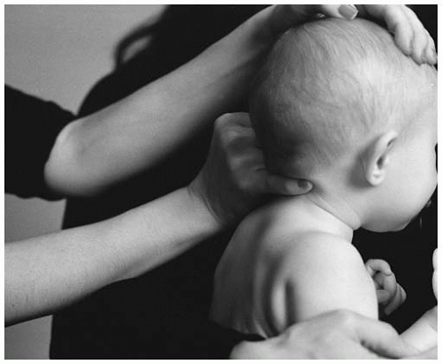
FIGURE 5-18 The fifth digit is placed on the posterior-inferior aspect of the occiput.


Static Palpation

Contact may be made by the fifth or second digit on the posterior-inferior (PI) aspect of the occiput (Fig. 5-18). Bogginess or edema may be detected if tissue injury is present. Posterior occiput rotation can palpate as soft tissue or bulging muscle.


Motion Palpation

The flexion or extension (-θX or +θX) range of motion is the primary motion to be evaluated. Contacting the condyle with the fingertips, slightly laterally flex the head to one side (Fig. 5-19). Once the articulation has been isolated, introduce a rocking motion consisting of flexion and extension. Repeat this procedure on the contralateral condyle. The PS condyle will manifest fixation during extension. The AS condyle will reveal joint restriction during flexion. To evaluate lateral flexion, slightly flex the head to the side approximately 5 degrees. Avoid creating unnecessary motion in the mid or lower cervical region. Normal lateral flexion will reveal a relaxation of the soft tissue components on the ipsilateral side of lateral flexion.


Instrumentation

The purpose of skin temperature analysis (e.g., Tempo-scope, Nervoscope) is to obtain objective neurologic evidence of a VSC and to monitor patient care. There is a probable connection between the nervous system and intersegmental variations in skin temperature (34). Studies have been conducted to assess the reliability of the use of temperature differential instrumentation (35,36).


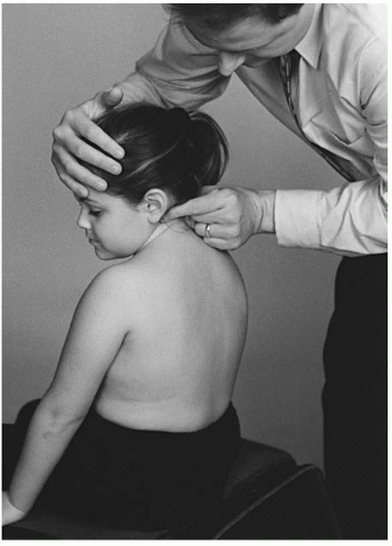
FIGURE 5-19 Motion palpation of the occiput.

The Temp-o-scope (Fig. 5-20) and other similar instruments provide a qualitative assessment of thermal asymmetry. The instrument detects the temperature on both sides of the spine. The method for conducting the exam is dynamic scanning. A bilateral skin temperature difference is depicted as meter needle movement to one side or the other. The “reading” or “break” in temperature symmetry is considered significant if an abrupt “over and back” needle movement is seen over a distance of one spinal segment. The amount of the temperature differential is thought to be directly proportional to the amount of neurophysiologic involvement due to the presence of VSC (37). The spinal subluxation in the acute stage often reveals a large variation in temperature. The temperature differential that diminishes gradually is interpreted as improvement in the aberrant neurophysiology. Monitoring the intersegmental heat differential is one of several parameters of assessing and gauging patient progress in response to specific spinal adjusting. Table 5.1 lists the corresponding segmental level of temperature differentials.

The procedure of scanning small sections of the spinal column one after another is recommended for
the paraspinal skin temperature instruments (35). To prevent the formation of air gaps at the skin and thermocouple interface, the probes are maintained in perpendicular contact with the skin surface using sufficient pressure. The scanning glide is caudad to cephalad for T2-C0 and cephalad to caudad for T2-S2 (S3 in the smaller patient). The nonamplified instrument should have a glide speed that does not exceed 0.5 to 1.0 cm/s (37). To confirm a suspected temperature differential at a segmental level, the scan should be repeated several times. The accentuated differentials with a repeated scanning procedure are considered more significant than those that diminish. The validity of the procedure is decreased when the existence of moles or other lesions (e.g., blemishes, scar tissue, cysts) are in the path of the instrument glide. The glide and orientation of the instrumentation is modified for the presence of spinal curvature (i.e., scoliosis). Because of the rolling, loose skin of the newborn/infant, any positive findings must be substantiated with other objective findings (e.g., tenderness or edema).


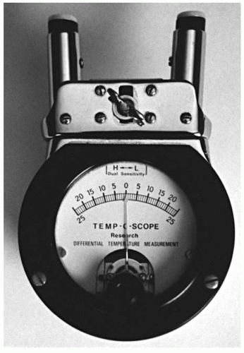
FIGURE 5-20 The Temp-o-scope.


TABLE 5.1


Corresponding Segmental Levels for Temperature Differentials (TDs)


C0-C2


The TDs occur very close together. A condyle or atlas subluxation may create a differential at any location between C2 and C0.


C2-T3


The TD should be inferior to the spinous process.


T4


The TD should be at the same level of the spinous process.


T5-T9


The TD should appear in the interspinous space above the spinous process of the involved vertebra.


T10-T12


The TD should be at the level of the spinous process.


L1-L5


The TD should appear at the level of the lower one-fourth of the spinous process.


Sacroiliac


The TD should appear anywhere between the superior boundaries of the inferior sacroiliac articulation.


Modified from Herbst RW. Gonstead Chiropractic Science and Art. Mt. Horeb, WI: Sci-Chi Publications, 1968; pp. 167-168.


The existence of an intersegmental temperature differential does not, by itself, determine the presence of the VSC. A spinal level with neurophysiologic involvement is not considered to be a subluxation when the presence of other subluxation parameters do not exist. Aberrant nervous system activity can occur at hypermobile functional spinal units (FSUs). Hypermobility of the FSU can be a compensation for a restricted and subluxated FSU at another level, typically below the hypermobile segment (38).

C0-C1 Temperature Scanning Procedure The neonate/infant is positioned across the lap or chest of the parent. The patient’s head should be maintained in a neutral position during the scan. The toddler and older child is seated on the cervical chair to perform the procedure. In the upper cervical region the temperature differentials occur close together. The close proximity of C0-C2 makes it difficult to determine the specific spinal level of the reading and must be confirmed with other objective findings. Suboccipital hair may also produce a spurious reading.


Radiographic Analysis

The lateral neutral posture of the occiput is analyzed in relationship to the atlas (see Chapter 4). The radiographic line that is drawn is called the foramen magnum line (FML). Because of the difficulty in identifying landmarks, assessing this region is performed by qualitative inspection. To create a maximal opening for the spinal canal, the foramen magnum line is fairly parallel to the AP atlas plane line. Deviation of the line in hyperflexion or hyperextension is considered abnormal. This
assessment can be further substantiated with stress radiographic studies in flexion and extension and clinical assessments (Fig. 5-21).


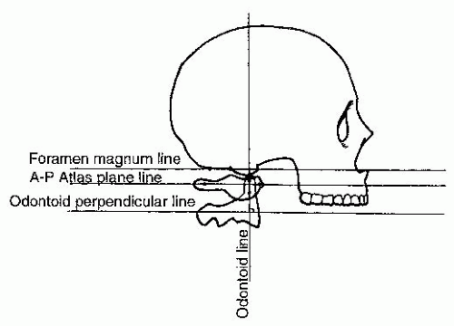
FIGURE 5-21 Relatively normal alignment of C0-C1. Modified from Herbst RW. Gonstead Chiropractic Science and Art Mt. Horeb, WI: Sci-Chi Publications, 1968; p. 133.

On the lateral radiograph the FML is altered in relationship to the AP atlas plane line. The FML will converge posterior on the AP atlas line with the AS condyle, reducing the space between the posterior arch of atlas and the foramen magnum. The PS condyle will appear as a convergence of the two lines anteriorly, increasing the space between the posterior arch of atlas and the foramen magnum.


TABLE 5.2


Occipital Condyle Listings


Gonstead Listing


International


Pattern of Thrust


PSRS


+θX, -θZ


Posterior to anterior, superior to inferior, right to left, through the Cθ-C1 joint plane line, with an inferior arcing motion toward the end of the thrust.


PSRSRA


+θX, -θZ, +θY


Posterior to anterior, superior to inferior, right to left, through the Cθ-C1 joint plane line; the head is prepositioned in right rotation.


PSRSRP


+θX, -θZ, -θY


Posterior to anterior, superior to inferior, right to left, through the Cθ-C1 joint plane line; the head is prepositioned in left rotation.


PSLS


+θX, +θZ


Posterior to anterior, superior to inferior, left to right, through the Cθ-C1 joint plane line, with an inferior arcing motion toward the end of the thrust.


PSLSLA


+θX, +θZ, -θY


Posterior to anterior, superior to inferior, left to right, through the Cθ-C1 joint plane line; the head is rotated toward the side of contact.


PSLSLP


+θX, +θZ, +θY


Posterior to anterior, superior to inferior, left to right, through the Cθ-C1 joint plane line; the head is prepositioned in right rotation.


AS


-θX, +Z


Anterior to posterior, superior to inferior, through the Cθ-C1 joint plane line.


ASRS


-θX, -θZ, +θY


Anterior to posterior, superior to inferior, right to left, through the Cθ-C1 joint plane line.


ASRSRA


-θX, -θZ, +θY


Anterior to posterior, superior to inferior, right to left, through the Cθ-C1 joint plane line; the patient’s head is prepositioned in right rotation.


ASRSRP


-θX, -θZ, -θY


Anterior to posterior, superior to inferior, right to left, through the Cθ-C1 joint plane line; the patient’s head is prepositioned in left rotation.


The AP open mouth (APOM) radiograph is used to determine if a right superior (RS) (-θZ), left superior (LS) (+θZ), or axial rotation (Y axis) exists. Lateral flexion positional dyskinesia (RS or LS) is determined by the transverse condyle line. The transverse condyle line is scribed by like points on both sides of the condyles. The like points are the mastoid notches (the grooves of the mastoid process on the temporal bones). Once the line has been drawn, it is compared to the atlas transverse plane line. It is considered to be normal when the two drawn lines are parallel in the coronal plane. A misalignment will manifest a divergence of the transverse condyle line from the atlas transverse plane line. An LS (+θZ) listing (divergence) will also appear as lateral flexion to the right side.

Condyle Y-axis rotation also is analyzed from the AP (APOM) radiograph. For a rotational subluxation to exist, it must also appear with a PS or AS and an LS or RS listing. If the condyle is in a rotational misalignment, the atlas will compensate with opposite rotation on the same side of misalignment. To list the condyle rotation, the atlas plane line is read for its axial compensation. The lateral mass of atlas will be smaller (posterior) if the condyle has rotated anteriorly. If the condyle has rotated posteriorly, the lateral mass of atlas will appear wider (anterior) to compensate for the axial rotation. The condyle rotation is listed as LP, LA, RP, or RA. The rotational misalignment should always be listed last (e.g., PSRSRP) (Table 5.2).


AS Condyle (-θX)

The AS condyle subluxation will reveal fixation and discomfort as the condyle is glided from anterior to posterior during motion palpation. Edema or bogginess is more difficult to assess. Lateral upright visual inspection will reveal a superior gaze to “the heavens.” The more severe the AS condyle subluxation, the greater likelihood of more severe neurological manifestations. A low Apagar score and depressed infant reflexes may be associated with this positional dyskinesia. The newborn or infant may be a slow developer or, in more extreme cases, can be at high risk (e.g., sudden infant death syndrome, sleep apnea). These patients have a tendency to be poor thrivers (e.g., low weight, poor appetite, weak cry). In the older infant, toddler, and preschooler, the parent may inform you that the child “head bangs” the crib or wall to fall asleep or when upset.

The AS condyle is not a common subluxation. It should be suspected if facial or brow trauma has occurred. Positions of in-utero constraint (e.g., brow or facial), obstetrical trauma, or a fall from a height (e.g., changing table, couch) are a few of the possible mechanisms of injury. An automobile accident with the child unrestrained or the toddler falling from a height and hitting the forehead can also induce the AS condyle subluxation. An unusual injury history given by the parent or guardian that does not correlate with typical AS injuries should alert the doctor to the possibility of child abuse.

The AS condyle adjustment is performed supine on the newborn and infant. The sitting position set-up is usually performed once the cervical musculature is developed (e.g., in the toddler or preschooler). A condyle block (Fig. 5-22) is used in all AS condyle adjustments. Once the correct size of condyle block is selected, it is placed under the cervical spine to support C1 to C7. The purpose of the condyle block is to stabilize the cervical spine when the thrust is performed.

Supine AS Condyle The newborn or infant is placed supine on the pelvic bench. The crown of the head is placed close to the edge of the table. Depending on the arc of thrust necessary for correction, the doctor will squat or kneel directly superior to the infant’s head. Once the condyle block is positioned, the parent can assist by gently holding the child in the supine position. The condyle subluxation without laterality or rotation will be corrected by contacting the glabella with both thenar eminences. The fingers will lightly wrap under the posterior occiput to create a slight lift (Fig. 5-23). A second hand set-up is the use of the second and third digits from both hands and contacting the glabella, with both thumbs wrapped under the posterior occiput to create a slight lift (Fig. 5-24). If condyle laterality exists, the doctor will position themselves slightly to the same side of the listing. If the listing is LS the contact hand will be the left and vice versa. The contact will be the soft portion of the doctor’s pisiform on the glabella (Fig. 5-25). The opposite hand will cup the posterior
occiput and create a slight separation from the atlas. The thrust is an arcing anterior to posterior and slightly superior to inferior movement. Laterality (e.g., PSLS, PSRS) is corrected by the doctor’s contact. To correct condyle rotation, the infant’s head is pre-positioned with slight rotation before the thrust. For posteriority (e.g., PSLSLP, PSRSRP), the head is slightly rotated away from the contact hand (Fig. 5-26). The anterior listing of PSLSLA or PSRSRA is pre-positioned with slight head rotation toward the side of the doctor’s contact hand (Fig. 5-27).


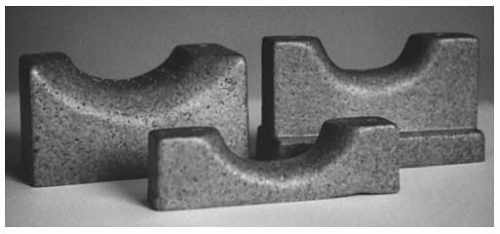
FIGURE 5-22 The condyle block comes in a variety of sizes to accommodate the cervical spine.


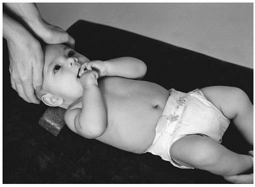
FIGURE 5-23 The thenar eminences contact the glabella for the anterior-superior occiput.


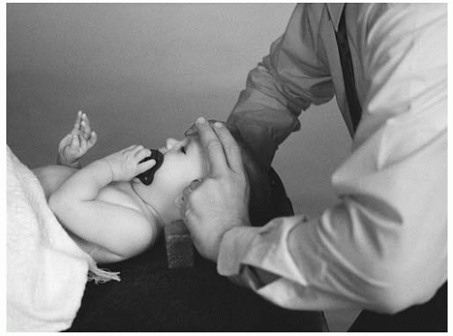
FIGURE 5-24 Fingers on the glabella with the thumbs wrapped around the posterior occiput.


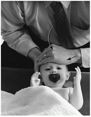
FIGURE 5-25 Single hand contact for an ASLS listing. The condyle block is used for all supine AS set-ups.


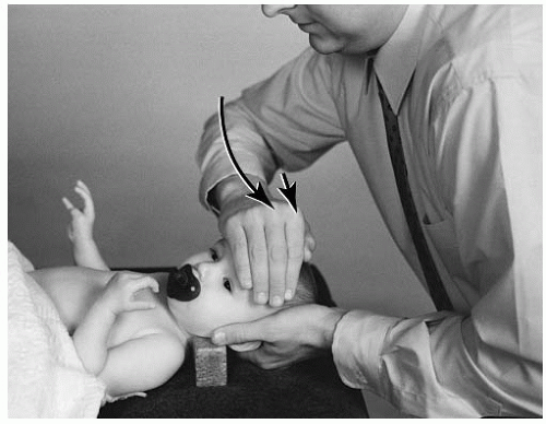
FIGURE 5-26 Slight head rotation of the infant’s head away from the contact hand will correct the axial rotation in an ASRSRP listing.


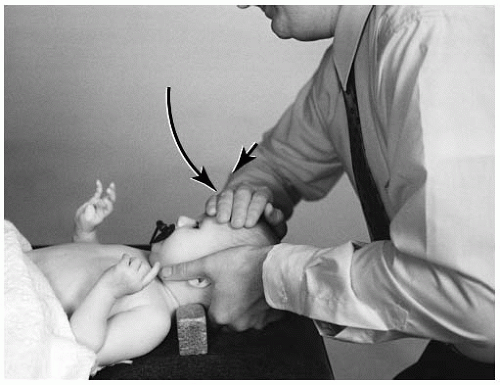
FIGURE 5-27 On the lateral side of occiput the doctor will squat or kneel behind the bench, contacting the glabella of the frontal bone on the side of laterality of the listing. The opposite hand will cup the posterior occiput and slightly lift to separate the occipito-atlantal joint. Head rotation toward the contact hand positions the infant for an ASRSRA listing.


Newborn and Infant


AS Condyle Supine Double Thenar Adjustment

Name of Technique: Gonstead.

Technique Procedure: Supine AS condyle double thenar adjustment.

Example: AS (-θX, +Z) (Fig. 5-28).

Contraindications: All other listings, hypermobility, normal FSU, instability, destruction of the cranium, fracture (pathologic or nonpathologic) of the frontal bone, infection of the contact bone, or fracture of the ocular orbit. Patient Position: Supine at the distal end of the pelvic table. The condyle block is placed underneath the cervical spine to protect the C1-C7 region.

Contact Site: The glabella.

Doctor’s Position: The doctor is kneeling or squatting cephalad to the patient.

Supportive Assistance: The parent holds the upper and lower limbs to keep them from moving.

Pattern of Thrust: Anterior to posterior, superior to inferior with an inferior arcing (scooping) movement across the lateral masses of C1.

Contraindication for the Thrust: The newborn is unable to be maintained in a supine position.


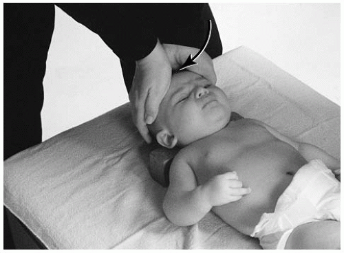
FIGURE 5-28 Supine AS condyle adjustment. Both thenar eminences are placed on the contact site. The fingers of both hands are wrapped around posterior to the occiput creating a slight lift. The doctor’s elbows should stay close to the side of the body.


AS Condyle Supine Finger Contact Adjustment

Name of Technique: Gonstead.

Technique Procedure: Supine AS condyle adjustment.

Example: AS (-θX, +Z) (Fig. 5-29).


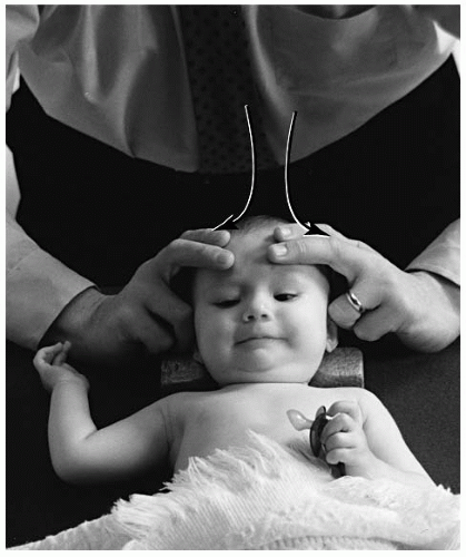
FIGURE 5-29 Supine AS condyle adjustment. Place the second and third digits of both hands on the contact site, the thumbs are wrapped around posteriorly to the occiput creating a slight lift. The doctor’s elbows should stay close to the side of the body.

Patient Position: Supine at the distal end of the pelvic table. The condyle block is placed underneath the cervical spine to protect the C1-C7 region.

Contact Site: The glabella.

Doctor’s Position: The doctor is kneeling or squatting cephalad to the patient.

Pattern of Thrust: Anterior to posterior, superior to inferior with an inferior arcing (scooping) movement across the lateral masses of C1.


ASRS Condyle Supine Adjustment

Name of Technique: Gonstead.

Technique Procedure: Supine ASRS condyle adjustment.

Example: ASRS (-θX, -θZ) (Fig. 5-30).

Patient Position: Supine at the distal end of the pelvic table. The condyle block is placed underneath the cervical spine to protect the C1-C7 region.

Contact Site: The glabella.

Doctor’s Position: The doctor is kneeling or squatting cephalad and to the side of laterality.

Supportive Assistance: The parent keeps the upper and lower limbs from moving.

Pattern of Thrust: Anterior to posterior, superior to inferior, lateral to medial with an inferior arcing (scooping) movement across the lateral masses of C1.

Seated AS Condyle The younger child (e.g., toddler or preschooler) may be positioned on the cervical chair. To accommodate the height of the child, an elevation device (e.g., pelvic bench pillow,
booster chair) may be used on the adjusting chair. The condyle block will be positioned behind C1-C7 and held there with the doctor’s abdomen (Fig. 5-31). The stabilization strap or the parent’s hand can also be placed on the child’s abdomen and chest to further stabilize the patient. For an AS listing, the flat palm of the doctor’s hand will contact the center of the glabella and supra orbital margin. The opposite hand will overlap the contact hand for stabilization (Fig. 5-32). An alternative set-up is for the doctor to interlink his or her fingers (Fig. 5-33). Pre-tension at the joint is obtained with slight head flexion. Before the thrust, the doctor’s elbows should be positioned close to the side of his or her body. This will provide for a smoother glide during the arc of the adjustment. Laterality is corrected by the doctor standing slightly toward the side of listing. The contact hand for a lateral misalignment (e.g., ASRS, ASLS) is the same hand as the side of listing. Condyle rotation (e.g., ASRSRP, ASLSLA) is corrected when the doctor pre-positions the head. For anteriority, the head is slightly rotated to the side of the contact hand (Fig. 5-34). Posteriority is corrected with slight head rotation away from the contact hand (Fig. 5-35).


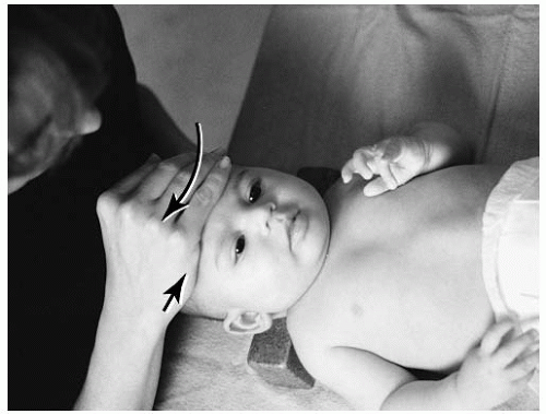
FIGURE 5-30 The doctor squats on the side of laterality, placing the right thenar eminence on the contact site for the ASRS listing. The stabilization hand is wrapped around the occiput, creating a slight lift. The doctor’s elbows should stay close to the side of the body.


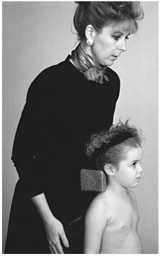
FIGURE 5-31 The condyle block is placed behind the patient’s C1-C7 spine. The doctor’s abdomen will hold the block.


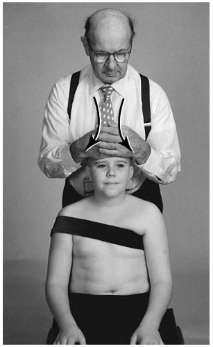
FIGURE 5-32 For the AS listing, the flat palm of the doctor’s hand contacts the center of the glabella, and the opposite hand will overlap the contact hand.


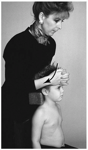
FIGURE 5-33 An alternative AS set-up is for the doctor to interlink his or her fingers.


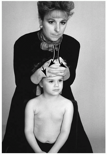
FIGURE 5-34 For the ASLSLA listing, the head is rotated to the side of hand contact.


FIGURE 5-35 The head is rotated away from the contact hand for the ASLSLP listing. The doctor’s elbows are kept close to his or her sides.


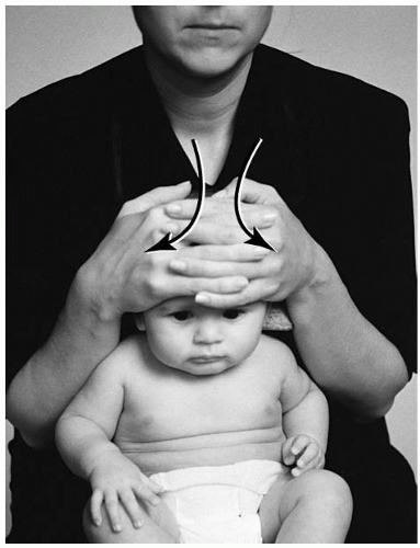
FIGURE 5-36 The infant is placed between the thighs of the doctor. The doctor places either thenar eminence on the contact site for the AS listing. The stabilization hand is placed on top. A second alternative is the doctor interlocking his or her fingers. The doctor’s elbows should stay close to the side of his or her body.


Infant


AS Condyle Seated Adjustment

Name of Technique: Gonstead.

Technique Procedure: Seated AS condyle adjustment.

Example: AS (-θX, +Z) (Fig. 5-36).

Patient Position: The infant is placed between the thighs of the doctor. The condyle block is placed underneath the cervical spine to protect the C1-C7 region.

Contact Site: The glabella.

Doctor’s Position: The doctor applies thigh pressure to the patient and support to the condyle block with his or her abdomen.

Pattern of Thrust: Anterior to posterior, superior to inferior, with an inferior arcing (scooping) movement across the lateral masses of C1.


Toddler and Preschooler


AS Condyle Seated Adjustment

Name of Technique: Gonstead.

Technique Procedure: Seated AS condyle adjustment.

Example: AS (-θX, +Z) (Fig. 5-37).


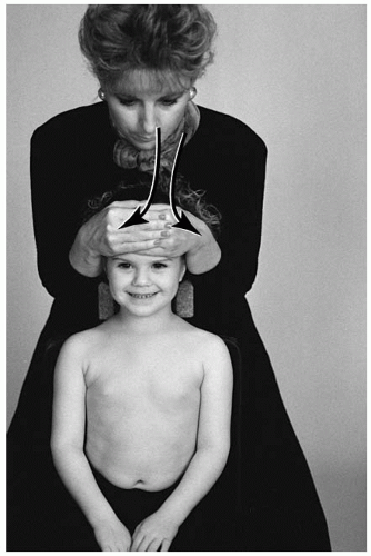
FIGURE 5-37 The smaller child may be raised in the chair by a pelvic pillow for the AS set-up. Either thenar eminence is placed on the contact site. The opposite (stabilization) hand is placed on top of the adjusting hand. A second option is for the doctor to interlock the fingers of both hands and placing them the contact site. The doctor’s elbows should stay close to the side of his or her body.

Patient Position: The patient is seated on the cervical chair. The child may need to be raised on the chair (e.g., using a pelvic pillow or booster chair). The condyle block is placed behind the cervical spine to protect the C1-C7 region. The stabilization strap can be used.

Contact Site: The glabella.

Doctor’s Position: The doctor stands behind the patient supporting the condyle block with his or her abdomen.

Supportive Assistance: The parent can support the upper chest to avoid movement.

Pattern of Thrust: Anterior to posterior, superior to inferior, with an inferior arcing (scooping) movement across the lateral masses of C1.

Contraindication for the Thrust: The toddler or preschooler is unable to be maintained in a seated position.


ASLS Condyle Seated Adjustment

Name of Technique: Gonstead.

Technique Procedure: Seated ASLS condyle adjustment.


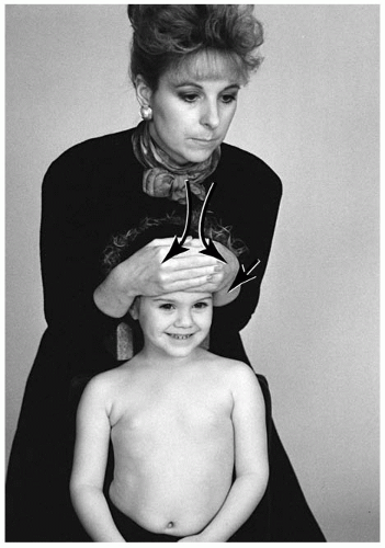
FIGURE 5-38 Seated ASLS condyle adjustment. The left thenar eminence is placed on the contact site. The stabilization hand is placed on top of the adjusting hand. The doctor’s elbows should stay close to the side of his or her body.

Example: ASLS (-θX, +θZ) (Fig. 5-38).

Patient Position: The patient is seated on the cervical chair. The condyle block is placed behind the cervical spine to protect the C1-C7 region. The stabilization strap may be used.

Contact Site: The glabella.

Doctor’s Position: The doctor stands behind the patient and slightly to the side of laterality. The doctor’s abdomen supports the condyle block.

Pattern of Thrust: Anterior to posterior, superior to inferior, lateral to medial, with an inferior arcing (scooping) movement across the lateral masses of C1.


Pre-adolescent and Adolescent


ASRSRA Condyle Seated Adjustment

Name of Technique: Gonstead.

Technique Procedure: Seated ASRSRA condyle adjustment.

Example: ASRSRA (-θX, -θZ, +θY) (Fig. 5-39).


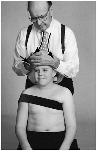
FIGURE 5-39 Seated ASRSRA condyle adjustment. The right thenar eminence is placed on the contact site. The stabilization hand is placed on top of the adjusting hand. The head is rotated slightly toward the doctor. The amount of rotation is in direct proportion to the amount of listing to be corrected. The doctor’s elbows should stay close to the side of his or her body.

Patient Position: The patient is seated on the cervical chair. The condyle block is placed behind the cervical spine to protect the C1-C7 region. The stabilization strap may be used.

Contact Site: The glabella.

Doctor’s Position: The doctor stands behind the patient and slightly to the side of laterality. The doctor’s abdomen supports the condyle block.

Pattern of Thrust: Anterior to posterior, superior to inferior, lateral to medial, with an inferior arcing (scooping) movement across the lateral masses of C1.

PS (+θX) Condyle The set-up for the newborn/infant is being seated on the lap of the parent. The child will sit with the side of laterality away from the parent. The doctor can use one of two contact points for the adjustment: the distal end of the thumb or the thenar eminence (of the doctor with small hands) will contact behind the infant’s ear and slightly above the mastoid process. The doctor’s stabilization hand will contact the contralateral cervical musculature, especially C1-C2. The fingers of the adjusting hand will wrap around the posterior aspect of the cervical spine. This method of stabilization will protect C1-C7 from receiving unnecessary motion during the thrust. Before the thrust, the parent should assist in stabilization by supporting the chest and back of the child. A second set-up is that the newborn/infant can be positioned between the legs of the doctor (Fig. 5-40). The chest or abdomen of the doctor will stabilize the child. Slight thigh pressure should be used by the doctor to prevent the child from shifting from the desired position.


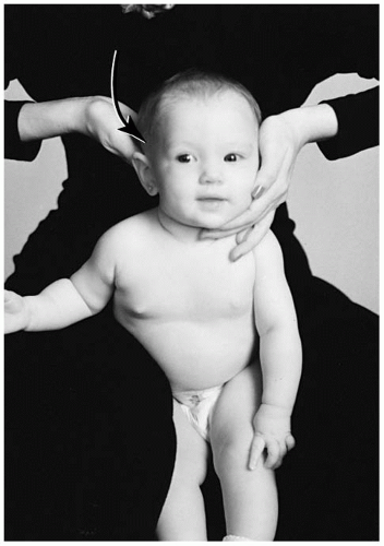
FIGURE 5-40 The infant can be placed between the thighs of the doctor. The doctor stabilizes with the chest or abdomen, combined with a slight medial thigh pressure.

The toddler, preschooler, or older child should be seated on the cervical chair. Chest stabilization can be attained with the parent’s hands or the stabilization strap. The doctor’s thenar eminence will contact the supramastoid groove on the side of listing (Fig. 5-41). To eliminate interference from occipital hair, the doctor will first glide superior from the supramastoid groove and then slide down to set up on the groove. The stabilization hand will contact the opposite
mastoid and the fingers will wrap around the C1-C2 articulation.


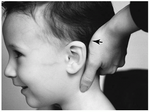
FIGURE 5-41 The doctor’s thenar eminence will contact the supramastoid groove on the side of listing.

Lateral flexion dyskinesia (e.g., PSLS, PSRS) will be corrected by contacting the mastoid on the side of laterality (Fig. 5-42). The pattern of thrust for a PSRS listing is posterior to anterior, superior to inferior, right to left, through the C0-C1 joint plane line, with an inferior arcing motion toward the end of the thrust. Condyle rotation is compensated for with pre-positioning of the patient. Anterior rotation (e.g., PSRSRA, PSLSLA) is corrected by slightly rotating the head toward the contact hand (Fig. 5-43). The posteriority listings of PSRSRP or PSLSLP are compensated by pre-positioning the child’s head slightly away from the doctor’s contact hand (Fig. 5-44).


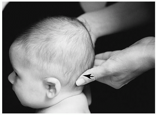
FIGURE 5-42 Set-up for a PSLS adjustment.


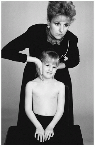
FIGURE 5-43 The head is rotated toward the doctor’s contact hand for the PSLSLA listing.


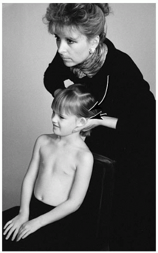
FIGURE 5-44 For the PSLSLP listing, the head is rotated away from the contact hand. The thrust is posterior to anterior, lateral to medial, with an inferiorward arcing movement.


Newborn and Infant


PSLS Condyle Seated Adjustment

Name of Technique: Gonstead.

Technique Procedure: Seated PSLS condyle adjustment. Example: PSLS (+θX, +θZ) (Fig. 5-45) listing.

Contraindications: All other listings, hypermobility, normal FSU, instability, destruction of the condyle fracture (pathologic or nonpathologic) of the condyle bone, infection of the contact bone.

Patient Position: The newborn/infant is placed on the lap of the parent. The involved side is facing the doctor. Contact Site: The left supramastoid groove.

Doctor’s Position: The doctor stands slightly to the side of laterality.

Supportive Assistance: The parent supports the chest and back region.

Pattern of Thrust: Posterior, superior to inferior, lateral to medial, with an inferior arcing movement across the lateral masses of C1.

Contraindication for the Thrust: The newborn is unable to be maintained in a seated position.


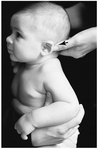
FIGURE 5-45 Seated PSLS set-up. The left distal end of the adjusting thumb or the thenar eminence is placed on the contact site. The stabilization hand supports the cervical musculature on the opposite side.


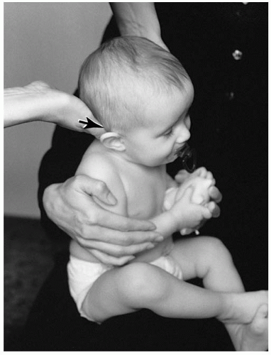
FIGURE 5-46 Seated PSRS listing. The right distal end of the adjusting thumb or the thenar eminence is placed on the contact site. The stabilization hand supports the cervical musculature on the opposite side.


PSRS Condyle Seated Adjustment

Name of Technique: Gonstead.

Technique Procedure: Seated PSRS condyle adjustment.

Example: PSRS (+θX, +θZ) (Fig. 5-46) listing.

Patient Position: The newborn/infant is placed on the lap of the parent, the involved side facing the doctor.

Contact Site: The right supramastoid groove.

Doctor’s Position: The doctor stands slightly to the side of laterality.

Supportive Assistance: The parent supports the chest and back region.

Pattern of Thrust: Posterior to anterior, superior to inferior, lateral to medial, with an inferior arcing movement across the lateral masses of C1.


Toddler and Preschooler


PSLSLA Condyle Seated Adjustment

Name of Technique: Gonstead.

Technique Procedure: Seated PSLSLA condyle adjustment.

Example: PSLSLA (+θX, +Z, -θY) (Fig. 5-47) listing.


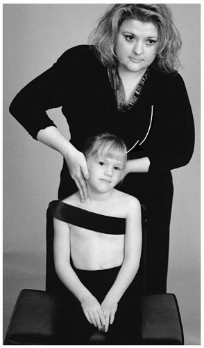
FIGURE 5-47 The PSLSLA condyle adjustment. The left thenar eminence is placed on the contact site. The stabilization hand is placed on the cervical musculature on the opposite side. The head is rotated toward the doctor. The amount of rotation is in direct proportion to the amount of listing to be corrected.

Patient Position: The patient is seated on the cervical chair. The child may need to be raised (e.g., using a pelvic pillow or booster chair). The stabilization strap can be used. Contact Site: The left supramastoid groove.

Doctor’s Position: The doctor stands behind the patient and slightly to the side of laterality.

Pattern of Thrust: Posterior to anterior, superior to inferior, lateral to medial, with an inferior arcing movement across the lateral masses of C1.


Pre-adolescent and Adolescent


PSRS Condyle Seated Adjustment

Name of Technique: Gonstead.

Technique Procedure: Seated PSRS condyle adjustment.

Example: PSRS (+θX, -θZ) (Fig. 5-48) listing.

Patient Position: The patient is seated on the cervical chair. The stabilization strap may be used.

Contact Site: The right supramastoid groove.


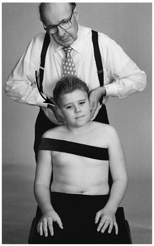
FIGURE 5-48 Seated PSRS condyle adjustment. The right thenar eminence is placed on the contact site. The stabilization hand is placed on the cervical musculature on the opposite side.

Doctor’s Position: The doctor stands behind the patient and slightly to the side of laterality.

Pattern of Thrust: Posterior to anterior, superior to inferior, lateral to medial, with an inferior arcing movement across the lateral masses of C1.


PSRSRP Condyle Seated Adjustment

Name of Technique: Gonstead.

Technique Procedure: Seated PSRSRP condyle adjustment.

Example: PSRSRP (+θX, -Z, +θY) (Fig. 5-49) listing.

Patient Position: The patient is seated on the cervical chair. The stabilization strap may be used.

Contact Site: The right supramastoid groove.

Doctor’s Position: The doctor stands behind the patient and slightly to the side of laterality.

Pattern of Thrust: Posterior to anterior, superior to inferior, lateral to medial, with an inferior arcing movement across the lateral masses of C1.


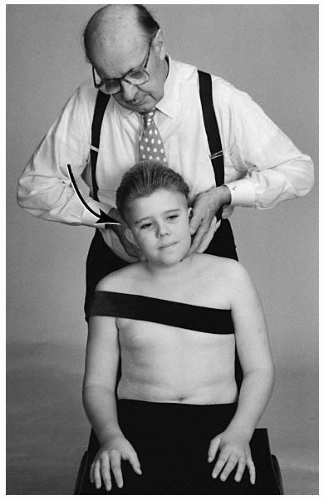
FIGURE 5-49 Seated PSRSRP condyle adjustment. The right thenar eminence is placed on the contact site. The stabilization hand is placed on the cervical musculature on the opposite side. The head is rotated away from the doctor. The amount of rotation is in direct proportion to the amount of listing to be corrected.


Atlas (C1-C2)

The atlas subluxation is not as common in the pediatric spine as one might first expect. Compensation in the upper cervical spine, particularly in the coronal plane, can result from a lower cervical subluxation. This is caused by the righting reflex. Examination of the atlas should involve a multiparameter approach. Relying on findings from the radiograph or static palpation alone is not sufficient to determine the need for an adjustment.

Inspection With the patient in a seated position, the doctor may inspect the atlas. If the atlas rotates posteriorly (e.g., ASLP, ASRP), the superficial muscle groups can bulge on the side of posteriority. The atlas that has rotated anteriorly (e.g., ASRA, ASLA) can present with a slight ipsilateral head tilt. To confirm lateral flexion malposition, request the patient to shut his or her eyes and then flex and extend his or her head for a few seconds. If lateral flexion fixation is present there may be a slight head tilt during the procedure or after resting in a neutral position.

Static Palpation Static palpation should be performed in the sitting position. The newborn or infant can be seated on the parent’s lap; the parent’s hands can support the chest and back of the child. The older child may be examined independently on a chair. The distal end of the fifth digit or the index digit is used to palpate the musculature. The static musculature examination is used to detect tissue edema or bogginess. The edema reaction at the tissues may be a response caused by autonomic nervous system dysfunction or trauma to the region. If posterior rotation is present, a bulging or increased musculature will be palpated. The examiner should be aware that muscular asymmetry or skeletal malformation can influence the validity of these examination findings.

Motion Palpation Motion palpation is conducted in the sitting position. As with static palpation, the parent may assist in the stabilization process of the smaller child or infant. The analysis of the atlas is to determine if fixation dysfunction is present in relationship to the axis (C2). The rotation and lateral flexion position of the atlas is ascertained with this procedure. The AS or AI component of the listing can be determined from the lateral radiograph.

To determine lateral flexion (±θZ), the doctor will need to contact bilaterally the transverse process of the atlas. The younger child can be contacted with the distal end of the fifth digit and thumb (Fig. 5-50 A,B). The larger child will be contacted with the second digit and thumb. The doctor should confirm the findings by reversing the palpation contact hand. This will reduce hand bias. With the doctor’s stabilization hand on the crown of the head, the doctor will laterally flex the head from side to side. Although the motion is not completely understood, it seems that the side contralateral to the fixation reveals the loss of motion. This appears as the lateral mass of C1 raised on the contralateral side when C1 is laterally flexed onto C2 (39). The listing is confirmed with the APOM radiograph. The lettering assigned is “R” for right or “L” for left after the AS (e.g., ASR, ASL) or AI (e.g., AIR, AIL).

The primary movement of the atlas-axis relationship is Y-axis rotation. Rotation (Y axis) can be determined very readily with motion palpation. First, place the distal end of the fifth or second digit at the anterior-lateral aspect of the transverse process of the atlas. Next, slowly rotate the head from side to side. The side of rotational fixation will reveal restriction.

On the older child, Dvorak’s maneuver can assist in determining if an upper cervical (C1-C2) rotational fixation is present. Flex the child’s head and rotate the spine from side to side (Fig. 5-51). The side of fixation will reveal restriction of motion. Once the side of laterality (±θZ) has been determined, rotation, if it exists,
must be determined. A posteriorly rotated atlas will be confirmed when the doctor can demonstrate restriction of that movement. A left posterior atlas (e.g., ASLP) will reveal restricted range of motion when the doctor rotates the patient’s head to the right. Likewise, a clockwise (+θ) restriction of the atlas reveals right posteriority (e.g., ASRP). The left anterior atlas (e.g., ASLA) is determined when the range of motion clockwise is restricted upon rotation. The ASRA listing is concluded when counterclockwise motion is diminished. The anterior “A” listing is often more difficult to determine.


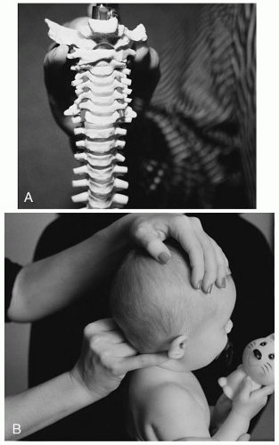
FIGURE 5-50 A,B: Depending on the size of the patient, the fifth or second digit will contact one side of the atlas transverse process. The thumb will contact the opposite transverse process.


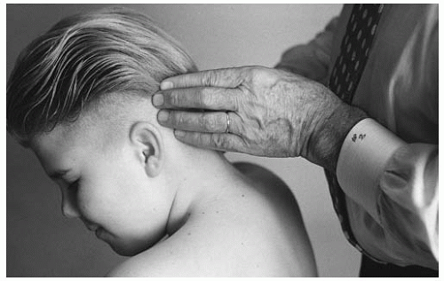
FIGURE 5-51 Dvorak’s maneuver may reveal rotational fixation in the upper cervical (C1-C2) region.


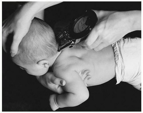
FIGURE 5-52 The infant’s baby fat may interfere with the gliding procedure. The parent or doctor may have to assist with a superiorward skin pull.

Instrumentation The newborn and infant are typically more difficult to assess with an instrument (e.g., Nervoscope, Temp-o-scope) than the older pediatric patient. What is commonly referred to as “baby fat,” or the brown fatty tissue present, can interfere with the gliding procedure (Fig. 5-52). With the toddler, the doctor must be careful to take into account that the child may move during the procedure, which leads to an inaccurate reading. Stabilization is required to maintain the subject in a motionless, neutral position (Fig. 5-53).
The procedure for this examination is to glide the instrument from caudad to cephalad. Suboccipital hair is also another factor that may give a false positive finding. If a true positive finding does occur, the doctor must further determine through other examination methods if the reading reflects a C1 or C2 involvement due to the proximity of the articulations.


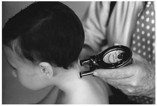
FIGURE 5-53 The doctor may stabilize the younger patient by bracing the shoulder or abdomen.

Radiographic Analysis When analyzing the atlas, it is important to acknowledge the possible active involvement of adjacent segments in compensation. The primary biomechanical motion of the atlas is rotation around the odontoid process of the axis. Therefore, the odontoid process is used as a reference point in the analysis of the atlas.

The lateral cervical radiograph is analyzed to determine the relationship between C1 and C2 (see Chapter 4). The odontoid will be divided with two dots. The first dot is placed at the base and center of the odontoid, the second dot at the center and superior aspect of the odontoid. Draw a longitudinal line intersecting the two points. This line is called the odontoid line. Through the mid-section of the body of the axis, draw a line perpendicular to the odontoid line. This line is referred to as the OPL.

To analyze the atlas, place one dot in the middle of the anterior tubercle, and a second dot at the middle junction of the posterior tubercle and the posterior arch. The line drawn between the two points is called the AP atlas plane line. Occasionally the lateral radiograph will reveal the atlas in a lateral flexion position. This will project a space between the posterior arch (rather than an overlap). In this case, bisect the space that the lateral atlas tilt creates. If the AP line and the OPL are parallel, a normal atlas and axis relationship can be assumed. Slight atlas extension onto the axis can also be considered to be within normal limits.

To evaluate the coronal plane posture, an open mouth projection is analyzed. The axis line is drawn parallel at the superior aspect of the body of axis, referred to as the “axis plane line (APL).” The APL represents the horizontal plane of atlas. To draw the line, choose two like points on the atlas. A reliable anatomical point is the transverse process-lateral mass junction. Often the superior border of the transverse process is obstructed by overhanging of the occiput. If this is the case then the dot should be placed on the inferior transverse process where it intersects the lateral mass. The two dots are connected with a line. A normal atlas-axis relationship is present when the atlas plane line and the APL appear parallel.

Anteriority (+Z) The atlas may slightly slide anteriorward as it rotates around the X axis. The transverse ligament is responsible for the close relationship of the atlas to the axis. Rupture or severe stretching of the transverse ligament should be suspected if noticeable anterior slippage is viewed on the lateral radiograph. The contact point for the adjustment for the atlas is the antero-lateral portion of the transverse process.

Superiority/Inferiority (±θX) The anterior tubercle can be referenced for the superiority or inferiority of the atlas on the lateral radiograph. Superiority or hyperextension positional dyskinesia is more common than inferiority/hyperflexion displacement. The superiority (-θX) misalignment is detected when the AP atlas plane line and the OPL diverge anteriorly. Inferiority, which is rare, can be detected when the AP atlas plane line and the OPL coverage anteriorly. The superior displacement is labeled “S” and follows the A listing. The inferior misalignment is given the letter of “I” and also follows the letter A. The listing of the atlas is AS or AI.

A second radiographic finding that can confirm the line analysis is to observe the space between the anterior portion of the dens and the posterior portion of the anterior tubercle of the atlas. When the AS listing is present this space will reveal an inverted “V,” the AI listing will appear as a “V.” It should be noted that the younger pediatric patient may show a marked space difference between the dens and tubercle. This increased atlas dens interspace (ADI) should not be interpreted as severe AS or AI misalignment. The normal ADI measurement of the pediatric spine is 1 to 5 mm. A greater measurement may be an indication of transverse ligament instability (e.g., a tear or sprain) or ligament absence, as seen in 25% of Down’s patients (14,40).

Laterality ±θZ (±X) The atlas can rotate around the Z axis and move toward the convexity of lateral bend (termed laterality). The AP radiograph is used to establish laterality. On the side of laterality, the atlas transverse plane will appear with a superior lift of the atlas from the axis plane line. The two possible listings of laterality are ASR or ASL. The ASR listing would reflect the divergence of the two lines on the right side.

Rotation +θY The AP radiograph is used to determine the fourth letter of the atlas listing (Table 5.3), which is the Y-axis rotational component. The anatomical reference points to determine rotation are the lateral masses of atlas. Rotation is listed on the side of atlas laterality (±θZ); if the atlas rotates posteriorly, the lateral mass will appear smaller. Anterior rotation of the atlas appears as a larger width of the lateral mass on the side of laterality. The possible listings are ASRP, ASLP, ASRA, and ASLA.


TABLE 5.3


Atlas Listings


Gonstead Listing


International


Pattern of Thrust


ASR


(+Z)>, -θX, -θZ,(-X)


Right to left, through the C1-C2 joint plane line, inferior arcing motion toward the end of the thrust.


ASRA


(+Z)>, -θX, -θZ, -X, +θY


Right to left, through the C1-C2 joint plane line, the head is rotated toward the side of contact, inferior arcing motion toward the end of the thrust.


ASRP


(+Z)>, -θX, -θZ, (-X), -θY


Right to left, through the C1-C2 joint plane line, the patient’s head is rotated away from the side of contact, an inferior arcing motion toward the end of the thrust.


ASL


(+Z), -θX, +θZ, (+X)


Left to right, through the C1-C2 joint plane line, an inferior arcing motion toward the end of the thrust.


ASLA


(+Z), -θX, +θZ, (+X), -θY


Left to right, through the C1-C2 joint plane line, the head is rotated toward the side of contact, an inferior arcing motion toward the end of the thrust.


AIR


(+Z), +θX, -θZ, (-X)


Right to left, through the C1-C2 joint plane line, superior arcing motion toward the end of the thrust.


AIRA


(+Z), -θX, -θZ, -X, +θY


Right to left, through the C1-C2 joint plane line, the head is rotated toward the side of contact, a superior arcing motion toward the end of the thrust.


AIRP


(+Z), -θX, -θZ, (-X), -θY


Right to left, through the C1-C2 joint plane line, the head is rotated away from the side of contact, a superior arcing motion toward the end of the thrust.


AIL


(+Z), +θX, + θZ, (+X)


Left to right, through the C1-C2 joint plane line, an superior arcing motion toward the end of the thrust.


AILA


(+Z), +θX, + θZ, (+X), -θY


Left to right, through the C1-C2 joint plane line, the head is rotated toward the side of contact, an superior arcing motion toward the end of the thrust.


ASLP


(+Z), -θX, +θZ, (+X), +θY


Left to right, through the C1-C2 joint plane line, the head is rotated away from the side of contact, an superior arcing motion toward the end of the thrust.


The indented concave surfaces of the lateral masses can be analyzed on the AP radiograph. Rotation can be analyzed by locating the radiolucency of the concave and indented upper medial surfaces of the lateral masses. The side of posterior rotation will manifest a narrower radiolucency and the anterior rotation will have a wider appearance.

A third method of analyzing the radiograph for rotation is by comparing the occiput-atlas relationship. The transverse occiput line may descend on the side of atlas anteriority. This may appear as a convergence of the transverse occiput line toward the atlas plane line.


C1-C2 Adjustment

The atlas adjustment is adapted to the age and compatibility of the pediatric patient. The neonate and the infant should be adjusted in a side posture or seated position. For the side posture set-up, the patient should be placed across the lap of the parent or on the pelvic table. If the patient is placed on the pelvic table, the doctor should evaluate the space between the lateral cervical spine and the table. A space >1/4A in. should be reduced by the placement of a folded towel or supportive foam to prevent this space from causing an uncontrolled drop phenomenon during the thrust (acceleration) phase.

The neonate or infant should be placed with the atlas listing-involved side up (e.g., ASR or ASL), the head and body in a neutral position, and the face toward the doctor. The practitioner should stand facing the patient. To eliminate the antero-lateral component of the listing (e.g., ASR or ASL) contact is made at the antero-lateral aspect of the transverse process of the atlas. The contact is made using the distal end of the fifth or second digit (Fig. 5-54). The distal stabilization digit (e.g., fifth or second) contacts the nail bed of the contact digit. The doctor’s forearms and stance should reflect the line of correction. To correct the posterior (“P”) component,
the doctor’s stance should be slightly leaning forward toward the patient. For the anterior (“A”) listing, the doctor’s stance should be slightly leaning away from the patient. The parent may assist by stabilizing the infant’s head and body.


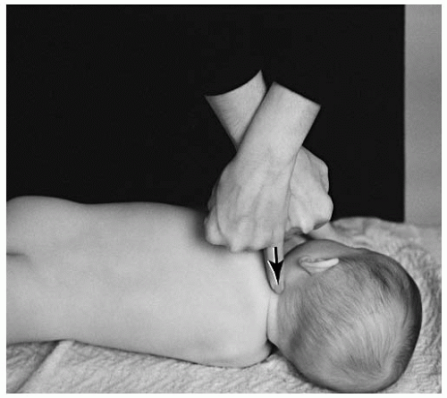
FIGURE 5-54 The atlas listing should be placed with the involved side up for a side posture set-up.

The sitting position is ideal for the infant or toddler. There are several possible sitting positions. The infant/toddler may be placed on the lap of an attending parent (Fig. 5-55). The parent should stabilize the child’s chest and mid-thoracic spine. The side of laterality should be placed toward the doctor for set-up. A taller doctor may place the infant/toddler between his or her legs and apply slight thigh pressure for stabilization (Fig. 5-56). This procedure should only be chosen if the doctor can maintain their contact and stabilization arms in proper alignment.

The toddler or older child may sit independently in a cervical chair with a back support. The stabilization strap or the parent’s hands are used to stabilize the chest. On the side of atlas laterality, the doctor will contact the antero-lateral aspect of the transverse of the atlas (e.g., ASR or ASL) with the distal portion of the thumb (Fig. 5-57). The rotational aspect of the listing (e.g., ASRP, ASRA, ASLP, ASLA) can be corrected by slightly rotating the head before the thrust. The posterior atlas (e.g., ASRP or ASLP) is corrected by turning the head away from the contact hand (Fig. 5-58). Anterior rotation (e.g., ASRA or ASLA) is corrected by rotating the head slightly toward the contact hand of the doctor. The opposite hand will be used to stabilize the opposite side of atlas laterality (Fig. 5-59). The stabilization hand will cup the ear and the fingers will point caudally to protect the C2-C3 articulation. The stabilization hand should not be used to create a counterforce. The thrust is given with a slight torque (+θX) to enhance the fluidity of the adjustment. A “set and hold” follows at the end of the adjustment.


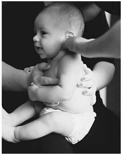
FIGURE 5-55 The infant may be placed on the lap of a parent for an atlas set-up. The parent will stabilize the infant.


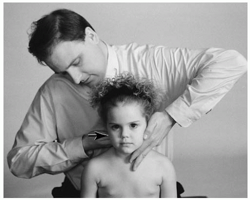
FIGURE 5-56 A taller doctor may place the toddler between his or her legs for an atlas set-up.


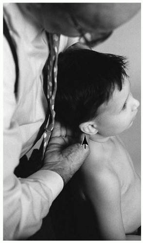
FIGURE 5-57 On the side of atlas laterality, the doctor will contact the antero-lateral aspect of the transverse process.


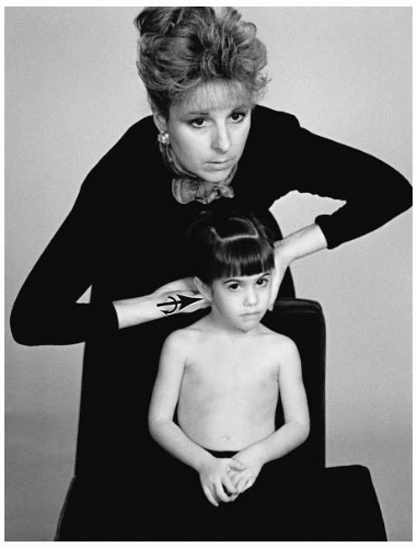
FIGURE 5-58 To eliminate the atlas posterior rotational listing, the head is rotated away from the contact site.


FIGURE 5-59 The head is rotated toward the side of the contact for the ASRA listing.


Newborn and Infant


CI ASL Seated Adjustment

Name of Technique: Gonstead.

Technique Procedure: Seated atlas adjustment.

Example: ASL (+Z, -θX, +θZ, +X) (Fig. 5-60) listing. AS (-θX) lateral flexion to the right (+θZ). Flexion and left lateral flexion fixation dysfunction.

Contraindications: All other listings, hypermobility, normal FSU, instability, pathologic fracture of the neural arch, infection of the neural arch or transverse process, destruction of the atlas, transverse ligament rupture.

Patient Position: The newborn/infant is placed in between the thighs of the seated doctor. The doctor applies slight thigh pressure.

Contact Site: Antero-lateral aspect of the transverse process of the atlas.

Supportive Assistance: The parent should keep the torso from moving.

Pattern of Thrust: Lateral to medial, with an inferior arc toward the end of the thrust.

Contraindication for the Thrust: The newborn/infant is unable to be maintained in a seated position.


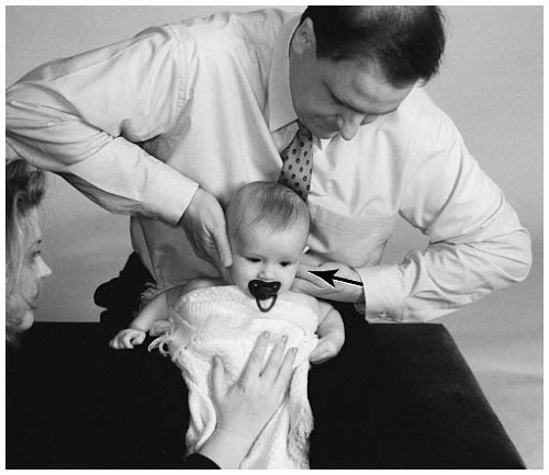
FIGURE 5-60 Seated ASL adjustment. The distal tip of the left thumb is on the contact site. The stabilization hand is placed cupping the opposite ear and stabilizing the C2-C3 articulation and the lateral musculature.


CI ASL Side Posture Adjustment

Name of Technique: Gonstead.

Technique Procedure: Side posture atlas adjustment.

Example: ASL (+Z, -θX, +θZ, +X) (Fig. 5-61) listing. AS (-θX) lateral flexion to the right (+θZ). Flexion and left lateral flexion fixation dysfunction.

Patient Position: The newborn/infant is placed on his or her right side on the pelvic bench. The head piece of the hi-lo or knee-chest table or the lap of the parent may be used. A small, rolled up towel or foam may need to be placed between the patient’s lateral aspect of the cervical spine and table to reduce any air gap.

Contact Site: Antero-lateral aspect of the transverse process of the atlas.

Supportive Assistance: The parent may need to stabilize the chest and/or lower limbs from activity.

Pattern of Thrust: Lateral to medial, with an inferior arc toward the end of the thrust.

Contraindication for the Thrust: The newborn/infant is unable to be maintained in a side posture position.


CI ASRA Seated Adjustment

Name of Technique: Gonstead.

Technique Procedure: Seated atlas adjustment.

Example listing: ASRA (+Z, -θX, -θZ, -X, +θY) (Fig. 5-62).

AS (-θX) lateral flexion to the left. Flexion and left lateral flexion, as well as right axial rotation fixation dysfunction.

Patient Position: The newborn/infant is placed in a seated position in the doctor’s lap. The doctor applies slight thigh pressure.

Contact Site: Antero-lateral aspect of the right transverse process of the atlas.


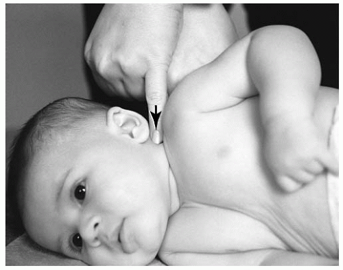
FIGURE 5-61 Set-up for a lateral ASLS listing. The distal tip of the fifth or second digit or thumb is on the contact site. The stabilization hand will support the contact hand by placing the fifth or second digit or thumb upon the nail bed of the contact hand.


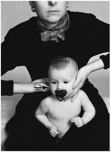
FIGURE 5-62 Seated ASRA adjustment. Distal tip of the right thumb is placed on the contact site. The stabilization hand is placed cupping the opposite ear and stabilizing the C2-C3 articulation and the lateral musculature.


Pattern of Thrust: Lateral to medial, with an inferior arc toward the end of the thrust.


Toddler and Preschooler


CI ASR Seated Adjustment

Name of Technique: Gonstead.

Technique Procedure: Seated atlas adjustment.

Example: ASR (+Z, -θX, -θZ, -X) (Fig. 5-63) listing. AS

(-θX) lateral flexion to the right (+θZ). Flexion and right

lateral flexion fixation dysfunction.

Patient Position: The toddler/preschooler is placed on

the cervical chair.

Doctor’s Position: The doctor stands behind and slightly to the side of laterality.

Contact Site: Antero-lateral aspect of the right transverse process of the atlas.

Supportive Assistance: The stabilization strap or the parent should keep the torso from movement.

Pattern of Thrust: Lateral to medial, with an inferior arc toward the end of the thrust.


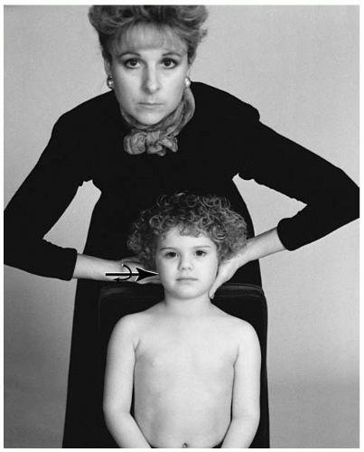
FIGURE 5-63 Seated ASR adjustment. The child may need to be raised on the chair by the pelvic pillow. The distal tip of the right thumb is on the contact site. The stabilization hand is placed cupping the opposite ear and stabilizing the C2-C3 articulation and the lateral musculature.


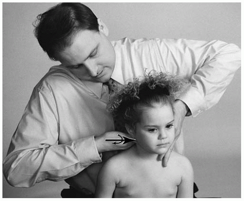
FIGURE 5-64 Seated ASRP adjustment. A taller doctor may place the patient between his or her thighs. The distal tip of the right thumb is on the contact site. To correct the rotational component (-θY), the head is slightly rotated away from the side of contact. The amount of rotation is in proportion to the rotational component. The stabilization hand is placed cupping the opposite ear and stabilizing the C2-C3 articulation and the lateral musculature.


CI ASRP Seated Adjustment

Name of Technique: Gonstead.

Technique Procedure: Seated atlas adjustment.

Example listings: ASRP (+Z, -θX, -θZ, -X, -θY) (Fig. 5-64).

AS lateral flexion to the left and right axial rotation.

Patient Position: The toddler/preschooler is seated between the thighs of the doctor.

Doctor’s Position: The doctor is seated on the pelvic bench or cervical chair.

Contact Site: Antero-lateral aspect of the right transverse process of the atlas.

Supportive Assistance: The stabilization strap may be used or a parent can stabilize the torso.

Pattern of Thrust: Lateral to medial, with an inferior arc toward the end of the thrust.


Pre-adolescent and Adolescent


CI ASL Seated Adjustment

Name of Technique: Gonstead. Technique Procedure: Seated atlas adjustment. Example listing: ASL (+Z, -θX, +θZ, +X) (Fig. 5-65). AS lateral flexion to the right side.

Patient Position: The patient is placed in a seated position on the cervical chair.

Contact Site: Antero-lateral aspect of the left transverse process of the atlas.

Pattern of Thrust: Lateral to medial, with an inferior arc toward the end of the thrust.


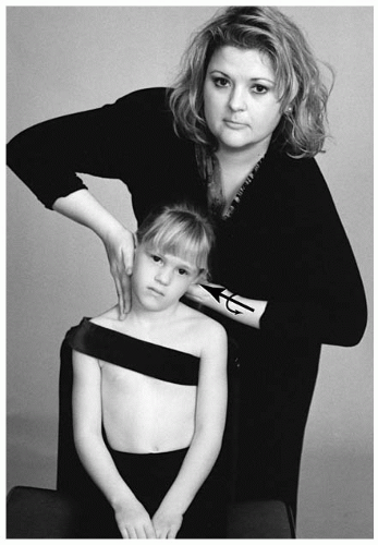
FIGURE 5-65 Seated ASL adjustment. The distal tip of the left thumb is on the contact site. The stabilization hand is placed cupping the opposite ear and stabilizing the C2-C3 articulation and the lateral musculature. Both arms should be opposed to each other when the set-up is completed.


CI AIL Modified Toggle Adjustment

Name of Technique: Gonstead.

Technique Procedure: Modified toggle atlas adjustment for the AI listing.

Example listing: AIL (+Z, +θX, +θZ, +X) (Fig. 5-66). AI lateral flexion to the right. Extension and right lateral flexion fixation dysfunction.

Patient Position: The patient is placed prone on the knee-chest or hi-lo table with his or her head rotated to the left side. To relax the paraspinal muscles, the arm of the involved side may be raised up over the patient’s head. Doctor’s stance: The doctor stands behind the patient.

Contact Site: Antero-lateral aspect of the left transverse process of the atlas.

Pattern of Thrust: Lateral to medial, with a superiorward arc toward the end of the thrust.


LOWER CERVICALS (C2-C7)

The cervical lordosis is formed by the wedge shape of the intervertebral discs (41,42). The magnitude of the lordosis is influenced by hyperplastic articular pillars (43), small facet angles (44), and short pedicles.


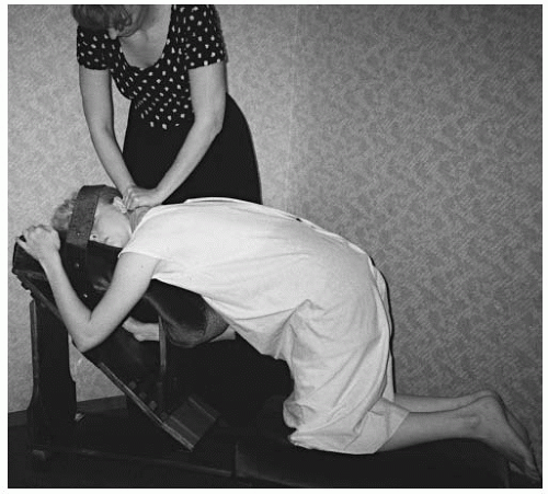
FIGURE 5-66 The modified toggle set-up is used for the AIL listing. The knee-chest table is suggested. The soft portion of the cephalad (right) hand is placed on the contact site. The caudad (left) hand will wrap around the adjusting hand.

The cervical curve was previously thought to develop after birth at approximately 4 to 6 months of age, when the cervical spinal muscles are beginning to be able to hold up the head. This, however, has been questioned. Bagnall et al. (45) suggests that at as early as 91\2 weeks (conceptual age), a well-defined secondary curvature can be demonstrated.


Inspection

A hypolordotic or kyphotic cervical curve is the most frequent reaction to cervical trauma or as a compensation to a vertebral subluxation. If the vertebral subluxation is in an extension (posterior and inferior) position, the vertebrae above will compensate in a flexion posture. Furthermore, the upper cervical region with hyperextension subluxations (e.g., AS occiput or AS atlas) can influence the mid-cervical spine with a corresponding postural kyphosis.

Rarely is hyperlordosis detected in the cervical spine. The thoracic spine can cause this type of postural reaction because of hyperkyphosis or compression fractures.


Motion Palpation

The zygapophyseal joints are part of a three-joint complex. The two zygapophyseal joints contribute greatly to the overall stability of the region. It should
be noted that the capsular ligaments are less taut in the cervical spine. This allows for increased range of motion.

The 45-degree angle (to the horizontal plane) of the zygapophyseal joints at C4 dictates the pattern of movement of the cervical vertebrae. At C7-T1 the facets are more vertical. There is a decreased +Z translation motion (anterior to posterior shear) at this level. In the lower cervical region the acuity of arc of movement is increased. The lower cervical arc is decreased with disc degeneration (46). This is seen more commonly in the mature adult spine. During flexion, the vertebrae will move anterior and superior. During extension the vertebrae will move posterior and inferior.

Coupling occurs with lateral flexion. At the segment level of C2-C3, for every 3 degrees of lateral flexion there are 2 degrees of axial rotation (46). The coupling mechanism decreases as you descend to the lower cervicals. At C7-T1, there is 1 degree of axial rotation for every 7.5 degrees of lateral bending (46).


Dynamic Response

Vertebral injury (causing adhesion formation or edema) or long-term effects of impaired postural movements can result in fixation dysfunction. Dynamic reaction is seen with hypermobility in the region above the level of hypomobility (vertebral subluxation). The mid-cervical region commonly will respond with a hypermobile dynamic reaction. The mid-cervical region of the adult has the highest incidence of disc protrusion and degeneration in the cervical spine (47). The mid-cervical spine also is a common site for traction osteophytes. This architectural response is a sign of hypermobility and/or instability. It is contraindicated to adjust hypermobile segments. The region of hypermobility is commonly more tender or painful on palpation because of the postural compensation for the hypomobile segments below. Stress radiographs may assist in determining specifically the hypo- and hypermobile segments of the pre-adolescent and adolescent patient.

There are two major types of motion palpation: “end play” and intersegmental range of motion. Current research suggests that “end feel” palpation is not reliable procedure (48). No intersegmental range of motion palpation studies have been performed. The reliability of motion palpation warrants further study within the chiropractic profession.

Intersegmental range of motion palpation is performed passively. Although the younger patient may inadvertently participate in this procedure, the examiner must be aware of this possibility and not hesitate to re-evaluate the region.

The position of the newborn and infant is typically prone on the parent’s lap or against the chest of the parent. It is important that the newborn or infant is stabilized in this position in a neutral plane by the doctor and/or parent. Once the palpation position has been attained, the doctor then determines which of his or her distal digits will be used to palpate the lower to mid-cervical region (C7-T1 to C2-C3).

The doctor should choose the distal digit that will be the most specific contact on the spinous process. Commonly, this will be the fifth digit (because of the smaller contact point) or the second digit for the toddler/preschooler spine (Fig. 5-67).

The contact will be made on the spinous process. With the opposite (stabilization) hand, the doctor contacts the crown of the infant’s head. To introduce passive motion for intersegmental range of motion, the examiner will lightly flex and extend the skull in a rocking glide. The normal finding at the joint is a nonrestrictive glide from posterior to anterior. If an extension positional dyskinesia (-θX, or posteriority and inferiority) is present, a restricted finding occurs when the spinous process does not complete the entire anterior (+θX, +Z) glide.

The posterior (-Z) listing is the most common among newborns and infants. In the newborn/infant through preadolescence, lateral flexion dyskinesia (±θZ) generally is not a major component of the listing. The superior or inferior wedge is analyzed from the AP radiograph. Lateral flexion dyskinesia is more likely to be detected when the extension dyskinesia (-Z, -θX, or posteriority and inferiority) is not positionally corrected. The two most common patient groups who have lateral flexion dyskinesia are younger children who may have a history of lateral cervical trauma or adolescents without previous or properly performed spinal care.


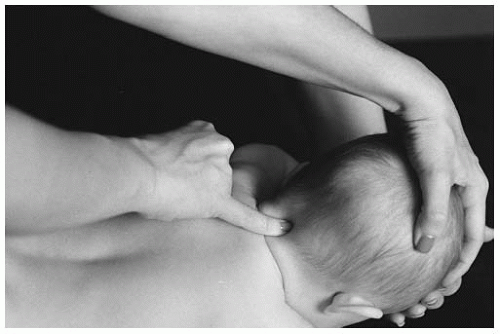
FIGURE 5-67 The distal end of the fifth digit contacts the spinous process of the cervical vertebra. The opposite hand supports the crown of the head.


To evaluate the pediatric spine for lateral flexion dyskinesia, the newborn/infant should be held in a sitting position by the parent. The parent should place one hand on the newborn or infant’s chest and the other on the mid-thoracic spine. The older patient should be seated. The doctor will place the smallest digit on one individual spinous process at a time (Fig. 5-68). Global motion palpation that attempts to scan two or more segments at a time is not encouraged (Fig. 5-69). The doctor will place the opposite (stabilization) hand on the crown of the head. From the neutral position, the doctor initiates the lateral bending of the cervical spine. The motion begins in the neutral position, and lateral bending is analyzed one side at a time. The soft tissue of the same or ipsilateral side of the bend will relax if there is no fixation of the segment. Generalized global scanning (e.g., left to right), although one form of analysis of the spine, should not be conducted as the primary or only assessment.

Assessing the coupling motion of spinous rotation PL and PR (±θY) is more difficult. As lateral bending occurs, the spinous process should rotate to the contralateral side of lateral flexion. This axial rotation is greater in the upper cervical region and decreases to a smaller coupling movement in the lower cervical region.


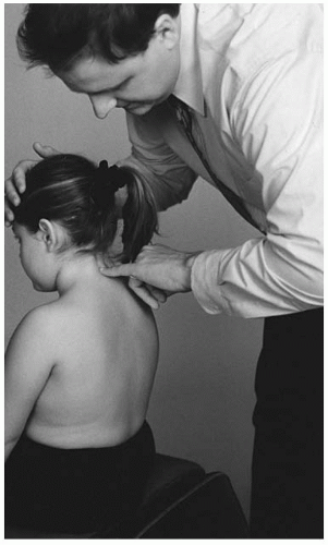
FIGURE 5-68 The doctor initiates the lateral bending of the cervical spine with the stabilization hand. The motion begins in the neutral position, and lateral bending is analyzed one side at a time.


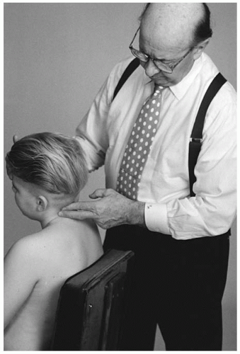
FIGURE 5-69 Global scanning of cervical segments is not recommended.

The occurrence of spinous rotation is not as common in the young spine (e.g., newborn/infant, toddler/preschooler). Suspect this positional dyskinesia in rotational trauma to the spine or the long-standing vertebral subluxation that is compensating for lack of proper segmental function elsewhere in the spine. If the direction of spinous rotation and lateral flexion dyskinesia is questioned, it should be confirmed with lateral flexion stress radiographs and the AP static view.


Instrumentation

The newborn/infant is placed in the prone position (Fig. 5-70). The older child is assessed in a seated position (Fig. 5-71). The hand-held instrument is glided caudad to cephalad. The loose skin of the newborn/infant should be considered as a possible confounding variable. To stabilize the younger child, the doctor may need to hold the crown of the head.


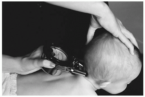
FIGURE 5-70 Stabilizing the cervical spine is necessary to prevent infant movement during instrumentation scanning.


Radiography

The neutral lateral cervical view is used to rule out any contraindications for the spinal adjustment. The lateral radiograph further provides analytical information about the position of the vertebral segment. Specifically hyperextended or flexed dyskinesia can be seen on this projection. Herbst (34) reveals that extension dyskinesia is highly correlated to segmental involvement.


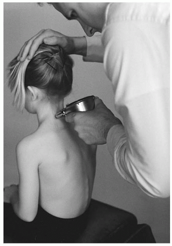
FIGURE 5-71 The instrument is glided inferior to superior on the cervical spine.

To confirm the finding, a flexion study would reveal little or no anterior to superior gliding. If the flexion study reveals appropriate +θX motion in relationship with the segment below, this cephalad segment is not indicated for a spinal adjustment. An exception to this contraindication is if a lateral flexion study reveals decreased bending (±θZ) or rotation (±θY).

The AP radiograph (coronal plane) is used to determine rotational (e.g., PL, PR) and lateral flexion (e.g., PLS, PRS, PLI-la, PRI-la) components of the subluxation listing (see Chapter 4 for line analysis). If the AP static listing does not correlate with the intersegmental motion palpation findings, lateral bending radiographs may be warranted to accurately determine the nature of the subluxation.

In lateral stress radiographs, coupling action occurs with axial rotation (Y axis) and slight flexion (X axis) because of the angle of the facet joints. At the segments of C7-T1 the facets (coronal plane) are similar to the thoracic spine. At this vertebral segment only slight coupled axial rotation is present.


Lower Cervical Adjustment

The age and compliance of the patient will determine the site for the cervical adjustment. The toddler may not be able to comply with the seated position; however; the preschooler through adolescent should have no difficulty with the cervical chair position.


Biomechanical Considerations in Adjusting the Lower Cervical Spine

When the subluxation of the segment is in extension, it is imperative to contact the spinous process and “lift” the segment to a flexed position (or posterior and superior). This corrective motion is +θX with +Z.

The neutral patient position seated in the cervical chair allows for the ideal set-up. In this position, the surrounding segments can be stabilized during the inferior to superior thrust. The recline of the chair is changeable; however, the most upright position is recommended. The stabilization strap is suggested for use on the taller child to prevent forward motion during the thrust. For the left-sided contact (e.g., PL, PLS) the strap is placed over the right shoulder (or the left shoulder for the right-sided contact). The smaller patient normally responds more easily to a parent stabilizing the child’s torso with his or her hand(s).

During the set-up preparation by the doctor, the use of excessive lateral flexion to create a pre-load tension on the contact site should be avoided. Slight lateral flexion can assist in the pre-tension of the segment of the joint. Because of the flexibility of the pediatric spine, exaggeration of this position will introduce excessive
coupling compensation and unnecessary spinous rotation. The set-up procedure for the chair adjustment is as follows:


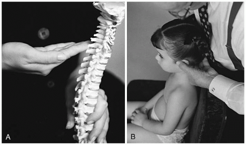
FIGURE 5-72 A,B: The first digit is supported by the second through the fourth digit as it contacts the spinous process or lamina listing.


  • Lower the patient’s head into a flexed position. The doctor will create a tissue pull in the line of correction.


  • With the first digit (distal, lateral, and palmar aspects), contact the inferior and lateral border of the spinous process or the medial aspect of the lamina (for lamina contacts).


  • The stabilization hand will assist in bringing the head into a neutral position and slightly posterior.


  • Slightly laterally flex (10 to 15 degrees) the head to the side of contact.


  • On the opposite side, place the stabilization hand on the cervical segments.


  • Following the line of correction, the contact hand and forearm will perform the thrust. The thrust is a very quick movement. The stabilization hand will not produce any force during the thrust.


  • After the adjustment, the segment that has been contacted should be held for a moment. This will allow for the viscoelastic elements of the segment to respond.


  • To protect the vertebral arteries and the ligamentous elements of the joint, the doctor should avoid positioning in or thrusting on the cervical spine with rotation or rotation with extension.

The pediatric patient should be seated in a neutral upright position. The legs should not be crossed and the hands should rest in a relaxed position on the lap. If the younger child is unable to touch their feet to the floor, they should be dangling in front of the chair.

The distal, lateral, and palmar regions of the doctor’s first digit are the contact points for the adjustment. To increase stability for the first digit, the second to fourth digits will be positioned behind as back-up (Fig. 5-72A,B). To set up on a spinous process listing (e.g., P, PL, PR, PLS, PRS), the distal inferior aspect will be contacted. The doctor should further compensate his or her stance to correct spinous laterality. If the listing is PR the doctor will slightly stand to the right side of the patient. Tissue pull is performed to eliminate tissue slack and increase specificity of the adjustment. For the PR listing, the stabilization hand will tissue pull from right to left and inferior to superior. The inferior to superior tissue pull is important in the lower cervical region to assist with correcting the extension (-θX) component of the listing.

In the pre-adolescent and adolescent, a lamina listing may be present (e.g., PLI-la, PRI-la). This finding is confirmed on the AP radiograph. The contact point is the medial aspect of the lamina. To correct the lateral flexion component, the lamina is contacted on the opposite side of the listing (i.e., the left lamina is contacted for PRI-la). The tissue pull is the same procedure as that used for the spinous process contact. The inferiority of the listing is corrected when, at the end of the thrust, a slight torque is introduced (clockwise for PLI-la and counter clockwise for PRI-la) by the doctor’s contact hand. Prepositioning in lateral flexion likely has a greater influence on the lateral flexion fixation than the torque movement.

To stabilize the contact hand, the thumb of the thrusting hand contacts the ramus of the mandible. During the thrust, no pressure should be exerted from the thumb into the ramus. The thumb will move slightly forward (posterior to anterior) during the thrust. Before, during, and after the thrust the contact hand should remain in the configuration of an arch (Fig. 5-73). The breaking of this hand posture increases the likelihood of introducing unnecessary rotation into the thrust.

On the opposite side of the thrusting hand the palmar side of the stabilization hand will contact the
cervical musculature (Fig. 5-74). The purpose of this contact is to stabilize the segments above and below the vertebra that will receive the thrust. The stabilization hand is not used to introduce any thrust or motion during the adjustment. To reinforce the vertebra that will be adjusted, the stabilization hand can distribute slight inferior pressure to the segment below. This will create a foundation to set the vertebra upon.


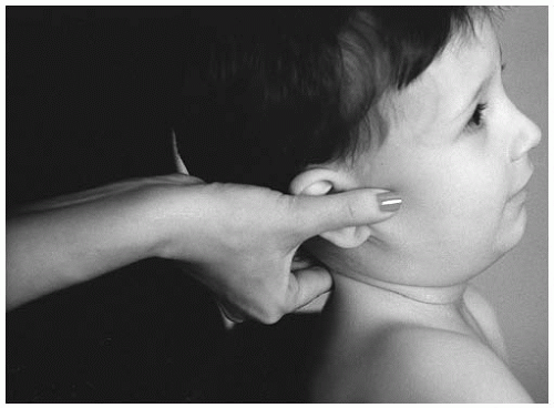
FIGURE 5-73 The thumb of the thrust hand contacts the ramus of the mandible. The contact should maintain an arch before and after the thrust.

With the taller adolescent, the posterior portion of the head can rest against the doctor’s chest or abdomen for stabilization. The smaller patient should be elevated in the chair (e.g., using a booster chair or pillow) to present the cervical spine for contact.

Considering the flexibility of the pediatric spine and, specifically, the component of elasticity, the following anatomical considerations, patient positions, or thrust vectors should be avoided. Contraindications for cervical adjustments include:


  • any other listing (i.e., set-up and thrust for a PR is performed as a PLI-la);


  • normal FSU is present;


  • infection of the contact vertebra;


  • fracture or destruction of the neural arch or spinous process;


  • long lever set-ups;


  • the doctor is contacting broadly (overlapping segments) with the adjusting hand;


  • bringing the segment to pre-tension with traction, extension, flexion, lateral flexion of rotation; and


  • producing a thrust with unnecessary vectors as stated in item 1.


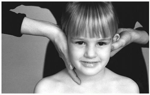
FIGURE 5-74 The palmar surface of the stabilization hand will contact the lateral cervical musculature.


TABLE 5.4


Examples of Adjustment Listings for the Lower Cervical Spine (C2-C7)


Gonstead


International


P (posteriority)


-Z


PL or PR


-Z, -θY or -Z, +θY


PLS or PRS


-Z, -θY, +θZ or -Z, +θY, -θZ


PLI-la or PRI-Ia


-Z, -θY, -θZ or -Z, +θY, -θZ


Table 5.4 presents different listings for the lower cervical spine (C2-C7).


Alternative Adjusting Procedures

The newborn, infant, and toddler may not adapt well to the seated position, so alternative positions are available. The newborn or infant can be placed in a prone position across the parent’s lap. The patient may also be placed across the lap of the doctor. If the latter is chosen, the doctor must be careful to align the adjusting forearm for a posterior to anterior thrust and not to introduce any rotation. A side posture position can also be chosen as long as the newborn/infant can be maintained in a neutral position (Fig. 5-75). The doctor should stabilize the crown of the infant’s head. Sitting
the patient in an upright position can be accomplished with the assistance of the parent. The parent will seat the infant in an upright position on their lap and support the chest and back with both hands (Fig. 5-76). The doctor should carefully stabilize the opposite cervical musculature to prevent the introduction of unnecessary forces to other segments.


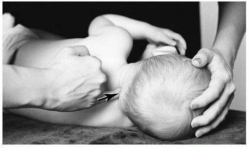
FIGURE 5-75 Placed in the side posture position, the spinous process is contacted by the distal end of the fifth digit.

The hi-lo or knee-chest table may also be an alternative for adjusting in a neutral position (Fig. 5-77A,B). If the two halves of the face pieces cannot be closed on the hi-lo table, rolling a small towel and placing it in the center may prevent the patient’s smaller face from hitting the bottom of the head piece during the thrust. When using the knee-chest table, the stabilization strap or parent’s hand may be used to stabilize the cranium. It should be noted that in the prone position, the cervical adjustment frequently does not create a pronounced audible.


Contact Digit and Stabilization

The parameters for choosing the contact digit are determined when the doctor evaluates the size of the involved vertebra and the suitable digit size that will specifically make the contact. A common doctor error is to choose the digit that he or she feels has the most coordination to deliver a thrust. This often results in choosing a digit that is too large (e.g., first digit of a
large male hand on the spinous process of a newborn) to specifically contact the segment, leading to overlap on additional segments.


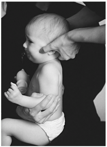
FIGURE 5-76 The older infant may be placed on the parent’s lap for a seated cervical set-up.


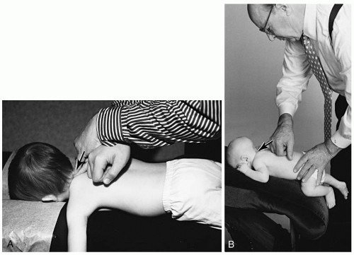
FIGURE 5-77 A: The hi-lo table may be used for cervical adjustments. B: The infant may be placed on the head piece of the knee chest table. The distal end of the fifth digit contacts the spinous process and the stabilization hand secures the infant’s position.

Particularly for the newborn, the traditional distal, palmar aspect of the second digit may not be specific enough. Depending on the size of the doctor’s fingers, the fifth digit may substitute for the second digit in the seated cervical adjustment.

Depending on the position of the patient (i.e., prone or sitting) and the cervical muscular development, the doctor can stabilize the contact digit. If an older infant is prone on the lap of the parent, the doctor’s contact is the distal end of the fifth digit. The use of the opposite hand for contact stabilization can only be used for the prone position. The second or fifth digit is placed on the contact nail bed. This stabilization procedure may be very helpful for those infants who manifest more developed cervical musculature.

Depending on the doctor’s contact position (single digit or double digit), the doctor or parent may stabilize the newborn/infant during the prone set-up by placing a hand on the crown of the skull.

Before the thrust, the doctor must evaluate the position of their forearm. The forearm reflects the line of correction. The primary listing of the vertebral subluxation for the newborn in particular, as well as the infant, is posteriority (-Z). The forearm placed in an incorrect position (lateral, too superior or inferior) should be properly aligned before the thrust.


Newborn and Infant


C2 Posterior Prone Adjustment

Name of technique: Gonstead.

Technique Procedure: Prone cervical.

Example: Posterior (-Z) C2 listing (Fig. 5-78).

Contraindications: All other listings, normal FSU, instability, hypermobility, destruction or fracture of the spinous process or neural arch, and infection of the contact vertebra.

Patient Position: The newborn/infant is placed prone across the lap of the parent or on the knee-chest or hi-lo table. If spinous rotation exists (e.g., PL, PR), the side of laterality faces toward the doctor.

Doctor’s Position: The doctor stands inferior to the patient.

Contact Site: The inferior lateral aspect of the spinous process.

Supportive Assistance: The parent should keep the upper torso and lower limbs from movement.

Pattern of Thrust: Posterior to anterior, inferior to superior, with an arcing movement through the plane line of the intervertebral disc and facet articulations.

Contraindication for the Thrust: The newborn/infant is unable to be stabilized in the prone position.


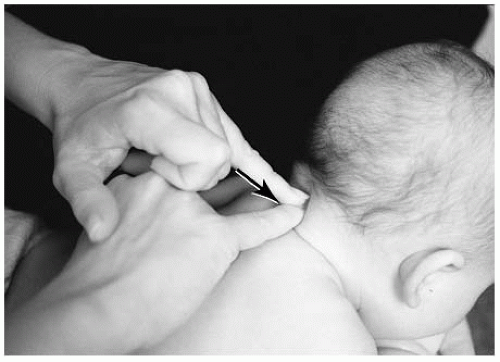
FIGURE 5-78 C2 posterior prone adjustment. The distal end of the fifth digit is placed on the contact site. To increase the depth of the thrust, the stabilization distal digit (e.g., fifth, second, thumb) will be placed on the adjusting nail bed. The doctor’s forearms should follow the plane line of the joint.


C3 Posterior Seated Adjustment

Name of Technique: Gonstead.

Technique Procedure: Seated cervical.

Example: Posterior (-Z) C3 listing (Fig. 5-79).


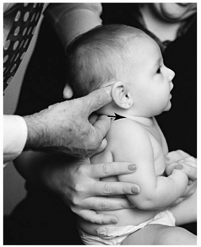
FIGURE 5-79 C3 posterior seated adjustment. The distal (and palmar) end of the right second digit is placed on the contact site. To increase adjusting hand stabilization, the third digit is placed next to the second digit. The palmar surface of the stabilization hand is placed on the opposite lateral musculature of the cervical spine. The thenar eminence of the stabilization hand is below the ear and thumb along the angle of the jaw. The doctor’s forearms should follow the plane line of the joint.


Patient Position: The newborn/infant is placed seated on the lap of the parent. If spinous rotation exists (e.g., PL, PR), the side of laterality faces toward the doctor.

Doctor’s Position: The doctor stands behind the patient.

Contact Site: The inferior lateral aspect of the spinous process.

Supportive Assistance: The parent should stabilize the chest and back of the patient.

Pattern of Thrust: Posterior to anterior, inferior to superior, with an arcing movement through the plane of the intervertebral disc and facet articulations. Contraindication to thrust: The newborn/infant is unable to be stabilized in the seated position, or if the doctor is unable to prevent excessive lateral flexion, extension, or rotation during the thrust.


Toddler and Preschooler


C7 PR Seated Adjustment

Name of technique: Gonstead.

Technique Procedure: Seated cervical chair.


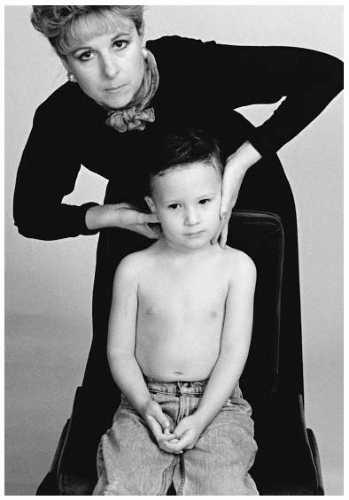
FIGURE 5-80 Seated C7 PR adjustment. The distal (and palmar) end of the right second digit is placed on the contact site. To increase stabilization of the adjusting hand, the third digit is placed next to the second digit. The contact hand thumb is placed on the ramus of the mandible. The contact thumb should not pull on the skin near the eye or be placed on the temporomandibular joint. The palmar surface of the stabilization hand is placed on the opposite lateral musculature of the cervical spine. The thenar eminence of the stabilization hand is below the ear and thumb along the angle of the jaw. The doctor’s forearms should follow the plane line of the joint.

Example: PR (-Z, +θY) C7 listing (Fig. 5-80). Patient Position: The toddler/preschooler is placed seated on the cervical chair. The child may need to be raised in the chair (e.g., using a pelvic pillow or booster chair). The cervical strap can be used.

Doctor’s Position: The doctor stands behind and slightly to the side of laterality.

Contact Site: The inferior right lateral aspect of the spinous process.

Pattern of Thrust: Posterior to anterior, inferior to superior, with an arcing movement through the plane of the intervertebral disc and facet articulations with a slight -θY rotation. The stabilization hand does not pull up during the thrust.

Contraindication for the Thrust: The toddler/preschooler is unable to be stabilized in the seated position, or the doctor is unable to prevent excessive lateral flexion, extension, or rotation during the thrust phase.


C6 PR Prone Adjustment

Name of technique: Gonstead.

Technique Procedure: Prone hi-lo cervical.

Example: PR (-Z, +θY) C6 listing (Fig. 5-81).

Patient Position: The toddler/preschooler is placed prone on the hi-lo table.

Doctor’s Position: The doctor stands on the right side and slightly inferior to the patient.

Contact Site: The inferior right lateral aspect of the spinous process.

Pattern of Thrust: Posterior to anterior, inferior to superior, with an arcing movement through the plane of the intervertebral disc and facet articulations with a slight -θY rotation.


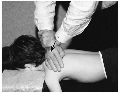
FIGURE 5-81 Prone C6 PR adjustment. The lateral border of the distal end of the right fifth metacarpal. To increase stabilization of the adjusting hand, the stabilization hand is placed on top of the adjusting hand with the fingers wrapped around the wrist.


Pre-adolescent and Adolescent


C5 PRS Seated Adjustment

Name of technique: Gonstead.

Technique Procedure: Seated cervical.

Example: PRS (-Z, +θY, -θZ) C5 listing (Fig. 5-82).

Patient Position: The patient is seated on the cervical chair. The cervical strap may be used.

Doctor’s Position: The doctor stands behind and slightly to the side of laterality.

Contact Site: The inferior right lateral aspect of the spinous process.

Set-up: The stabilization hand is placed on the top of the patient’s head. The head should be slightly flexed to separate the spinous processes. The contact digit is placed on the contact site. The head is brought up to a neutral position by the stabilization hand and then positioned on the contralateral musculature of the cervical spine. To relax the posterior musculature, the chin is raised slightly. The cervical spine is laterally flexed slightly (10 to 15 degrees) to the side of laterality. To pre-load the joint, a posterior to anterior (+Z) pressure is applied with the contact digit. Head movement is restricted by the stabilization hand during the thrust. The stabilization hand does not pull up during the thrust.


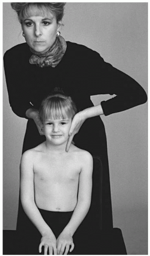
FIGURE 5-82 Seated C5 PRS adjustment. The distal (and palmar) end of the right second digit is placed on the contact site. To increase stabilization of the adjusting hand, the third digit is placed next to the second digit. The thumb of the contact hand is placed on the ramus of the mandible. The palmar surface of the stabilization hand is placed on the opposite lateral musculature of the cervical spine. The thenar eminence of the stabilization hand is below the ear and thumb along the angle of the jaw. The doctor’s forearms should follow the plane line of the joint.

Pattern of Thrust: An arcing movement posterior to anterior and inferior to superior, with a slight -θY rotation through the plane of the intervertebral disc and facet articulations. At the end of the thrust, a slight counterclockwise torque is applied through the right center of mass of the segment that enhances right lateral flexion of the vertebra.

Contraindication for the Thrust: The patient is unable to be stabilized in the seated position, or the doctor is unable to prevent excessive lateral flexion, extension, or rotation during the thrust phase.


C5 PRI-LA Seated Adjustment

Name of Technique: Gonstead.

Technique Procedure: Seated cervical.

Example: PRI-la (-Z, +θY, +θZ) C5 listing (Fig. 5-83).

Patient Position: The patient is seated on the cervical chair. The cervical strap may be used.


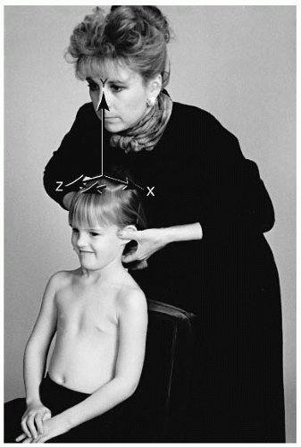
FIGURE 5-83 Seated C5 PRI-la adjustment. The distal (and palmar) end of the left second digit is placed on the contact site. To increase stabilization of the adjusting hand, the third digit is placed next to the second digit. The thumb of the contact hand is placed on the ramus of the mandible. The palmar surface of the stabilization hand is placed on the opposite lateral musculature of the cervical spine. The thenar eminence of the stabilization hand is below the ear and thumb along the angle of the jaw.


Doctor’s Position: The doctor stands behind the patient and slightly to the opposite side of spinous process laterality.

Contact Site: The medial portion of the left lamina.

Set-up: The stabilization hand is placed on the top of the patient’s head. The head should be slightly flexed to separate the spinous processes. The contact digit is placed on the contact site. The head is brought up to a neutral position by the stabilization hand and then positioned on the contralateral musculature of the cervical spine. To relax the posterior musculature, the chin is raised slightly. The cervical spine is laterally flexed slightly (10 to 15 degrees) to the side of contact. To pre-load the joint, a posterior to anterior (+Z) pressure is applied with the contact digit. Head movement is restricted by the stabilization hand during the thrust. The stabilization hand does not pull up during the thrust.

Pattern for the thrust: An arcing movement posterior to anterior and inferior to superior, with a slight +θY rotation through the plane of the intervertebral disc and facet articulations. At the end of the thrust, a slight counterclockwise torque is applied through the left center of mass of the segment that enhances left lateral flexion of the vertebra.

Contraindication for the Thrust: The patient is unable to be stabilized in the seated position, or the doctor is unable to prevent excessive lateral flexion, extension, or rotation during the thrust phase.


C2 PR Knee Chest Adjustment

Name of Technique: Gonstead.

Technique Procedure: Knee chest prone cervical.

Example: PR (-Z, +θY) C2 listing (Fig. 5-84).


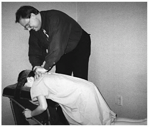
FIGURE 5-84 C2 PR knee chest adjustment. The lateral aspect of the right fifth metacarpal is placed on the contact site. The stabilization hand is rested on top of the adjustment hand. The doctor’s forearms should follow the plane line of the joint.

Patient Position: The pre-adolescent or adolescent is positioned on the knee-chest table. The head strap is secured to stabilize the cervical region.

Doctor’s Position: The doctor stands inferior and to the side of spinous process laterality.

Contact Site: The inferior lateral aspect of the spinous process.

Pattern of Thrust: Posterior to anterior and inferior to superior, with an arcing movement through the plane of the intervertebral disc and facet articulations.

Contraindication for the Thrust: The patient is unable to be stabilized in the knee chest position.


THORACIC SPINE

The thoracic spine often manifests a compensation to a subluxation in a different spinal region. Full spinal analysis is necessary to eliminate the possibility of introducing a force into a compensatory area. The adjustment should only be performed at fixated segment(s). Lateral bending stress radiographs can assist in determining which segments are hypomobile compared with the hypermobile (compensatory) articulations.

Important considerations for thoracic analysis of the vertebral subluxation are the anatomical factors (e.g., facet planes, ribs, etc.), mechanism of injury, and the extent of kyphosis. The thoracic spine often is trau-matized while the child is in a flexion position. If injury occurs in a flexed position, the damaged ligaments are unable to support the motion segment, resulting in a flexion malposition (49). The spinal segment should be adjusted at the level of flexion trauma.

The thoracic spine is limited in its ability to compensate in a sagittal or extension plane. The adolescent spine can compensate by creating a “dishing” effect, particularly at the T1-T6 region (50). The compensated dish region is usually painful, edematous, and responsive to compressive palpation (+Z). The adjustment should occur at a segment caudal to the compensatory region.

Only gold members can continue reading. Log In or Register to continue

Stay updated, free articles. Join our Telegram channel

May 24, 2016 | Posted by in PEDIATRICS | Comments Off on Spinal Examination and Specific Spinal and Pelvic Adjustments

Full access? Get Clinical Tree

Get Clinical Tree app for offline access