Sacro-Occipital Technique for the Pediatric Patient


Sacro-Occipital Technique for the Pediatric Patient


Martin Rosen


These procedures are based on the concepts, philosophy, and techniques developed by Major Bertrand De Jarnette, DO, DC. In instances in which De Jarnette had no specific protocols for the pediatric patient, his techniques have been modified or supplemented with applicable procedures to work with these patients.

The protocols in this chapter have been limited to newborns to children aged 3 years. Though all of these procedures can be used for the older pediatric patient, the specific needs for the 3 years and older age group usually require other procedures and protocols not covered in this text. In the cranial section, the adjusting techniques and evaluation procedures are applicable to all pediatric patients; it is designed to give the chiropractor a basic understanding of cranial physiology and adjusting techniques.


PHILOSOPHY, ART, AND SCIENCE OF THE SACRO-OCCIPITAL TECHNIQUE

“The only true subluxation you ever see must be in a child prior to the age of 7 years. If this subluxation goes uncorrected it becomes a primary source of stimulus through life, but the tombs of distortion, which form from one traumatic experience to the other, soon bury this primary subluxation under that ‘tomb of distortions’… The subluxation that all of us worry about occurred some time between birth and the seventh year of life, and the remedy would of course be careful chiropractic care from birth through the seventh year of life” (1).

De Jarnette made this statement in his 1967 text The Science Art and Philosophy of SOT (1). Even during the early stages of the development of his technique, De Jarnette understood the long-term ramifications of the subluxation and its affect on the functioning potential of the human nervous system.

Sacro-occipital technique (SOT), as developed by De Jarnette (2,3), is based on a category system of classifying subluxation patterns into three distinct and identifiable yet interrelated systems of body reaction. Through the use of specific indicators, the location and correction of these subluxation patterns are made (4,5,6).

Category I addresses the primary respiratory mecha nism or system between the sacrum and occiput (Chart 28-1). This is thought to be the initial insult or subluxation to the human nervous system. When this system subluxates, usually because of dural meningeal stress at the upper cervical region, cranium, or anterior sacroiliac (SI) joint, it puts a strain on the spinal and cranial dura and impedes the flow of cerebrospinal fluid (CSF) throughout the spinal-cranial system. This dural involvement creates distortion patterns and spinal and cranial subluxations in response to compensatory reactions caused by this primary subluxation.

Category II involves hypermobility of the SI joint causing a disruption in the relationship between the sacrum and its corresponding ilium (Chart 28-2). The SI weight-bearing subluxation causes neural compromise as well as structural compensatory patterns because of loss of the body’s ability to maintain itself against gravity. This subluxation pattern involves the cranial sutural system, the spine, and extremities and often disrupts the normal functioning of the temporomandibular joint. Failure to correct this category II complex or the body’s inability to compensate for the stress of this subluxation pattern usually leads to a myriad of structural subluxations and compensations and eventually to the category III subluxation complex.

Category III is a complete failure of the compensatory reaction from a primary subluxation (usually category I
or II) and brings about neural compromise as a result of nerve root compression or stretch syndrome caused by direct involvement of the cartilaginous (discs) joints of the spine. Spinal degeneration and long-term neurological and histological changes are direct parameters of this subluxation pattern (Chart 28-3).


CHART 28-1 Sacro-occipital technique adjusting protocols category I.

In the pediatric patient doctors usually deals with either category I or category II subluxation patterns because degenerative subluxation patterns (category III) are not usually present. The SOT category system gives the chiropractor a set of indicators and checks and balances that may not only help uncover the subluxation but also determine when a positive neurological change has occurred after the adjustment. This is extremely important in pediatric care when subjective determinations or indicators are not very useful. SOT gives the practitioner a variety of ways to make an adjustment, from the standard forms of osseous (high velocity/low amplitude) structural corrections to lower force and meningeal corrective procedures, a must when dealing with the delicate spine and nervous system of an infant.


CHART 28-2 Sacro-occipital technique adjusting protocols category II.

SOT also encompasses a complete array of adjusting procedures and protocols to determine the type of subluxations present and the most efficient way to correct them. From spinal structural corrections to meningeal and tonal evaluation protocols, viscerosomatic subluxation patterns, extremity evaluation procedures, and cranial corrective procedures, SOT provides the chiropractor with a neurologically based indicator system.

SOT is designed to assist the chiropractor in locating and correcting the primary subluxation. This is accomplished through evaluation of indicators relating to specific category subluxation complexes.


CHART 28-3 Sacro-occipital technique adjusting protocols cervical major.


EXAM PROCEDURES FOR INFANTS TO 3-YEAR-OLDS

This presentation will cover in detail those examination procedures that are specific to the SOT protocols. Standard examination procedures are also a vital part of the initial examination and should be used in conjunction with these SOT specific procedures to get a full picture of the neurological and structural state of the pediatric patient.
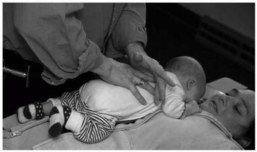
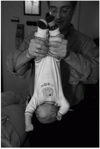
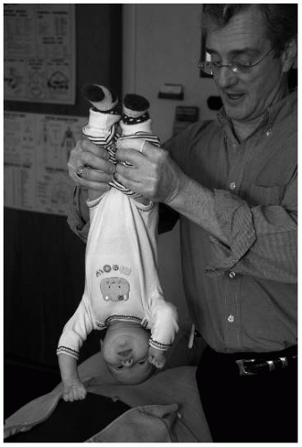


FIGURE 28-1 Inverted swing test.


Inverted Swing Test

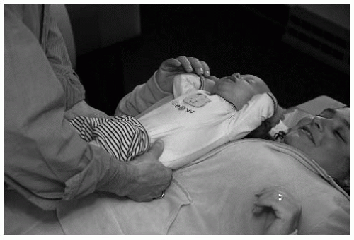
Grasp the infant with one hand under the occiput while the other hand holds the shins. If the infant is too large, then grasp the shins only, one in each hand. Slowly raise the infant off the table until he or she is suspended fully upside down. Gently induce a mild swinging motion. A normal child will hang relaxed and unconcerned. If the child laterally bends or rotates his or her head, it may be evidence of a cervical subluxation (Fig. 28-1).

If the child exhibits a short leg, this suggests a category II subluxation. If the legs remain balanced but the child tenses, then a possible category I is present. Finally, if the head flexes or extends or there is significant blanching and flushing, then a cranial lesion is possible (for indicators, see “The Cranium” later in this chapter). Contraindications for this procedure include hydrocephaly, hip dysplasia, recent head trauma, and cranial shunts.


Condylar System Evaluation

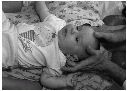
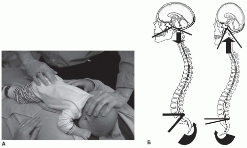
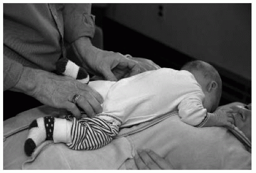
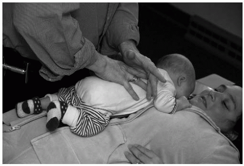
Atlanto-Occipital Restriction Contacts are made bilaterally, with the fingers on the occipital bowl and the thumbs contacting the right and left frontal region (Fig. 28-2). The clinician holds the skull lightly and bends it laterally, moving the chin to both the right and left. The side of restriction is the side of the subluxation. It is important to bend laterally the condylar system without involving the cervical spine.


FIGURE 28-2 Atlanto-occipital restriction analysis.

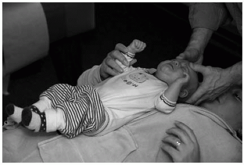
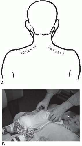
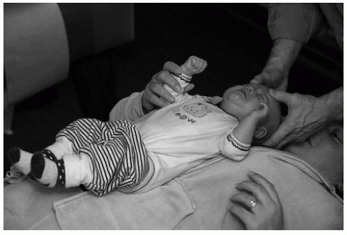
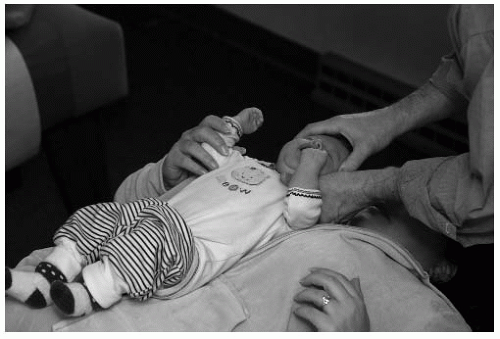
Atlas Occipital Decompression This is caused by a hyperextension trauma (usually during the birth process) and is found by extending and flexing the infant’s occiput upon the atlas (Fig. 28-3). The clinician holds the child’s occiput with a four-finger contact while placing the thumbs anterior to the ear then gently rocks the head into extension then flexion. If there is restriction while trying to bring the head into flexion, then the occipital condyles are shifted anterior in relation to the atlas.

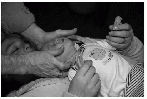
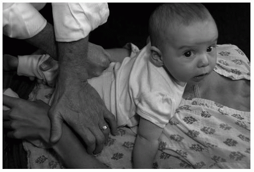
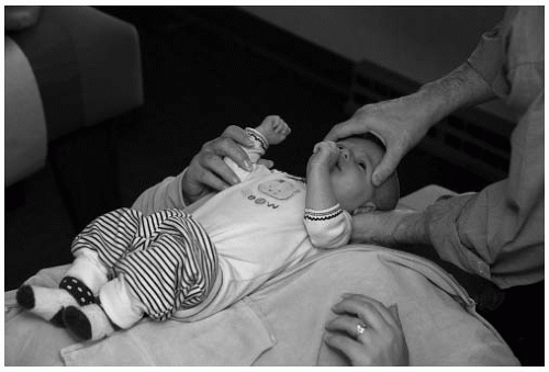
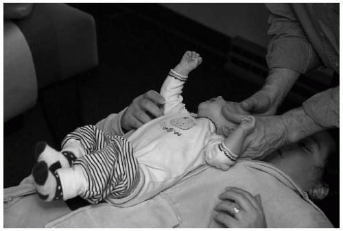
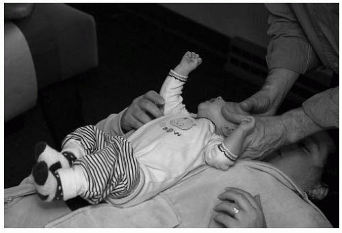
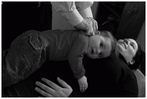
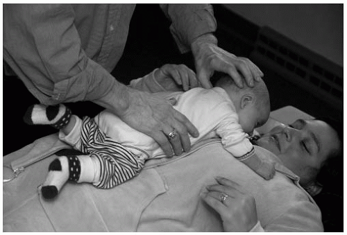
High Occiput The doctor can palpate the tension at the atlas occipital condyles bilaterally (Fig. 28-4). The side with the most tension plus restricted range of motion (ROM) is the side of the high occiput, especially during side bending or lateral flexion. Visual analysis may also show a high occiput in the prone and seated positions. With the patient in the prone position, the chin will tend to deviate towards the side of the high occiput.


Cervical Spine Evaluation

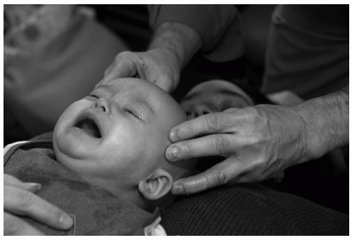
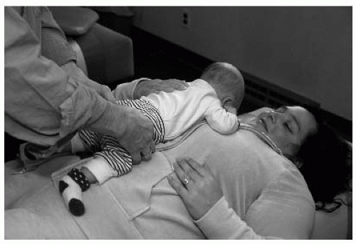
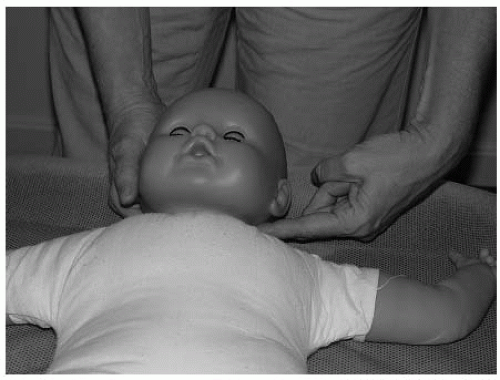
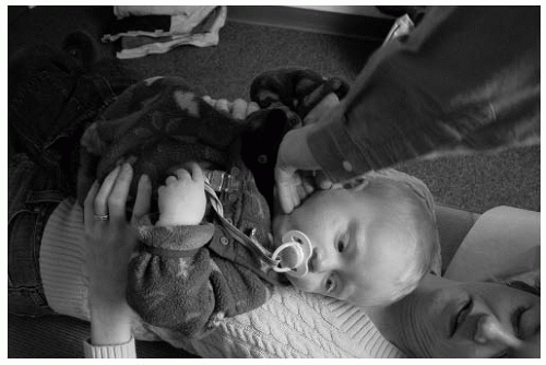
Cervical Stairstep Cervical stairstep can be performed on an infant as long as the clinician can get the child to relax, although it is easier to evaluate older children once cervical motor control has be obtained (Fig. 28-5). The clinician places the child supine on top of the parent or adjusting table then spreads the fingers so that the index and middle fingers are in front of the ear and the ring and little fingers are behind the ear. The thumbs gently rest on the parietals approximately ¾ in. from the suture, with no pressure over the bregma. The clinician then gently compresses the head and cervical spine straight caudally, making sure the face and chin remain parallel to the ceiling and the head is not flexed or extended. As a caudal pressure is gently applied, the doctor feels four distinct steps, beginning at the cervical thoracic junction. These represent the motion of the motion segments of the cervical spine: T1-C7 (step 1), C6-C5 (step 2), C4-C3 (step 3), C2-C1 (step 4). If a step locks, the subluxation is at that level and one of fixation. If a step skips and goes past to the next step, the subluxation may be one of hypermobility at that level.


FIGURE 28-3 Atlas occipital decompression.


FIGURE 28-4 High occiput.

Global Neck Mobility Neck mobility is important when considering central nervous system (CNS) dysfunction or disease. Suppleness or rigidity may be determined by the clinician cradling the child’s head in his or her hands while facing the child’s head while the child is in the supine position. The clinician moves the head in all directions and notes any resistance, especially during flexion.


FIGURE 28-5 Cervical stairstep.


FIGURE 28-6 Sacroiliac mobility.


Sacral Motion

SI Mobility SI mobility should be equal on each side. With the child in the supine position, the doctor places the thumb of each hand on the anterior superior iliac spine and the index finger on the posterior superior iliac spine (PSIS) (straddling the ilium) then gently applies a rocking motion to each innominate in an anteroposterior direction, feeling for normal motion (Fig. 28-6).

Sacro Occipital Reciprocal Motion Technique Placing one hand on the sacrum parallel to the spine and the other on the occiput perpendicular to the spine (Fig. 28-7), the doctor feels for reciprocal motion. During inhalation the sacral base moves posterior and caudal and the occiput moves inferior and anterior into flexion. The reverse is true during exhalation/extension: the sacral apex moves posterior and caudal whereas the occiput moves posterior and superior.


FIGURE 28-7 A: Sacro-occipital motion. B: SOR motion.


FIGURE 28-8 Sacroiliac subluxation.

The doctor can also rotate (Y axis) the occiput and sacrum in opposite directions and feel for the freedom of movement. If a restriction is present in reciprocal or rotational ranges of motion, then the clinician should also check C2 and C3 for subluxations. Correction of C2 or C3 should be done during the next visit.

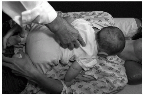
SI Subluxation The doctor presses directly over the SI joint on each side of the pelvis (Fig. 28-8). The infant crying or showing signs of discomfort suggests sacral subluxation. In this situation, when the doctor is correcting
SI subluxations, the corrective force is directed to the sacrum and its relationship to the ilium. All corrective forces will be applied directly to the sacrum. If the parent states that the child is difficult to diaper, especially if the infant struggles or will not separate his or her legs, a possible sacral dural pull subluxation may be indicated.


FIGURE 28-9 Palpation of dollar sign.

Palpation and Evaluation of the “Dollar Sign” A positive “dollar sign” indicator is present when the area designated as the dollar sign (where the gluteus medius, minimus, and maximus and the piriformis converge) is palpated and either a hyper- or hypotonicity is detected (Fig. 28-9). A dollar sign refers to an area the size of a silver dollar in an adult; in a young child this size is smaller, closer to a quarter or a 2010 dollar coin. Its location is approximately 2 in. inferior to the PSIS and an inch lateral.

Pain and discomfort may be elicited on one side in relation to the other. In pediatrics the dollar sign that is the most taut or tender is considered to be major, and it is the one that should be corrected first. A major dollar sign is indicative of meningeal or dural subluxations that tend to have more of a global effect on the CNS.

The doctor uses his or her thumb or index finger to palpate the tension in each dollar sign. Mild to moderate pressure is used at the central aspect of the dollar signs in a posteroanterior direction.

Palpation and Evaluation of the Crest Sign A positive crest sign is present when there is increased tension on one side in relation to the opposing crest. It usually is indicative of a predominantly structural musculoskeletal subluxation complex that will respond well to more structurally oriented techniques or high-velocity/lowamplitude adjustments.

To locate the active or major crest sign, the thumbs gently roll off the crest of the ilium 1 in. lateral to the spinous process at the level of L4 and press gently medially toward the spine (Fig. 28-10). Increased tissue resistance or tension in this area (where the quadratus lumborum and erector spinae intersect) is indicative of a positive crest sign in need of correction.


FIGURE 28-10 Palpation of crest sign.


Specific Reflex Thoracic and Lumbar Evaluation Procedures

Trapezius Fiber Analysis The trapezius fibers are located from the acromioclavicular V to just lateral to the transverse process of T1 (Fig. 28-11). They are numbered
one through seven; fiber 1 is at the acromioclavicular V, and fiber 7 is lateral to the transverse process of T1. The fibers are palpated with the thumbs from the lateral aspect of the transverse process of T1 (fiber 7) to the acromioclavicular V. In infants, about 2 lb of pressure at fiber 7 is used. The clinician gradually decreases the pressure as he or she palpates laterally to fiber 1. The examiner is feeling for an increased tension, nodulation, or discomfort at a specific fiber. This is considered to be an active trapezius fiber and is diagnostic of a straight inferior tippage (hyperextension) of the involved vertebrae. Once an active fiber is found, the doctor palpates the related thoracic or lumbar vertebrae spinous process to elicit either a pain response or swelling at the inferior aspect of the involved spinous process (Table 28.1). Restriction will be felt when attempting to move the spinous in an inferior superior direction.


FIGURE 28-11 A: Trapezius fibers. B: Trapezius fiber evaluation.


TABLE 28.1


Trapezius Fiber Correlation


Trap Fiber


1


2


3


4


5


6


7


Thoracic


1,2,10


3,11,12


4,5


6


7


8


9


Lumbar


1


2


3


4


5


Trap fiber


1


2


3


4


5


6


7


Thoracic


1,2,10


3,11,12


4,5


6


7


8


9


Lumbar


1


2


3


4


5


FIGURE 28-12 A: Occipital fiber location. B: Occipital fiber palpation. C: Occipital fiber anatomy.

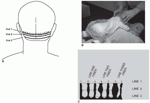
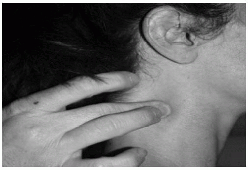
Occipital Fiber Analysis There are seven occipital fibers located from just lateral to the external occipital protuberance to the occipital mastoid V (Fig. 28-12). The fibers are evenly spaced with fiber one starting at the occipital mastoid V and the seventh fiber just lateral to the external occipital protuberance.

There are three occipital lines, each containing seven fibers, located directly below each other from the superior nuchal line to the inferior nuchal line. For the purposes of this section, the author will be discussing lines one and two. Palpation of the fibers is done by placing the index fingers at the occipital mastoid V (fiber 1) and the middle finger directly below and slightly behind it. The middle finger then gently tractions the tissue laterally as the index finger palpates the line 1 fiber. As the clinician moves from fiber 1 to fiber 7, the index finger stays slightly in front on the middle finger as it gently tractions the tissue laterally to make the fiber more accessible.


A line 1 fiber feels like a taut, slightly swollen string and is usually painful. The line 2 fiber is a slightly swollen nodulation directly below the line 1 fiber. Once the doctor finds a line 1 fiber, he or she should palpate directly below it to determine if it has progressed to a line 2 fiber. Generally, there is not a line 2 fiber unless there is an active line 1 fiber directly above it. If only a line 1 fiber is found, then the related vertebra (see chart below for correlations) is adjusted according to line 1 protocols; however, if the fiber extends into line 2, then only line 2 adjustment protocols are to be used.

Resistance and Contraction (R&C) Factors for Lumbar Subluxation Evaluation These indicators are based on the “Lovett Brother” relationship between the cervical and lumbar vertebrae. Proprioceptors and nociceptors located in the vertebral joints create reflex neurological compensations in structural distortion patterns. This phenomenon can be monitored and used to determine structural subluxation patterns in related vertebra. Cervical indicators can give the practitioner a clue to the possible presence and position of lumbar subluxations. The R&C relationships are as follows: C1-L5, C2-L4, C3-L3, C4-L2, and C5-L1 (Fig. 28-13). Palpation just posterior to the cervical transverse processes will detect a slightly swollen, tense nodulation that often may be painful, and further palpation of the lateral aspects of the cervical bifurcated spinous processes may also have similar active indicators. In the case of the atlas vertebra, palpation of the styloid process is the correct indicator. Active indicators at the cervical transverse process is indicative of a lumbar spinous rotation to the ipsilateral side of the related lumbar vertebra, whereas an active spinous or styloid indicator is indicative of lumbar spinous inferiority on that cervical side (Table 28.2).


FIGURE 28-13 Resistance and contraction factor location.


TABLE 28.2


Resistance and Contraction Factors


Cervical Involved


Lumbar Involved


Cervical Indicator


Lumbar Position


Styloid


L5


Styloid


Inferior tippage


Atlas


L5


Transverse process


Spinous rotation


Axis


L4


Spinous process


Inferior tippage


Transverse process


Spinous rotation


C3


L3


Spinous process


Inferior tippage


Transverse process


Spinous rotation


C4


L2


Spinous process


Inferior tippage


Transverse process


Spinous rotation


C5


L1


Spinous process


Inferior tippage


Transverse process


Spinous rotation


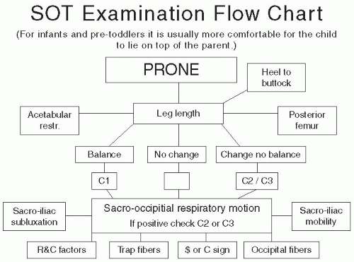
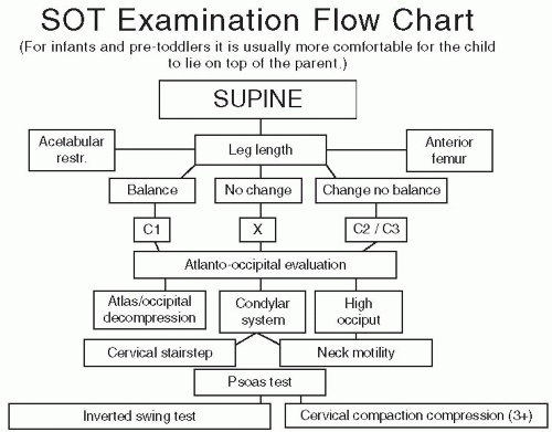
Leg Length Discrepancy The doctor should perform a leg length examination in both the prone (Fig. 28-14) and supine positions (Charts 28-4 and 28-5). The doctor tractions the child’s legs inferior while maintaining tension on the Achilles tendons and checks for a length imbalance. Once the short leg length has been established, the parent or an assistant may gently rotate the child’s head left and right as the doctor continues to gently traction the legs inferior while looking for a change in the leg length.

1. For the child in the supine position, the doctor places his or her index finger across the Achilles tendon and the thumb across the cuneiforms.


FIGURE 28-14 Prone leg discrepancy exam.


CHART 28-4 Examination flow chart prone.


CHART 28-5 Examination flow chart supine.


FIGURE 28-15 Acetabular restriction.

2. For the child in the prone position, the doctor straddles the Achilles tendon with his or her thumbs and index fingers at the base of the ankle with the rest of the hand wrapped around the plantar surface of the foot.

As the child’s head is turned, the doctor maintains a steady traction while observing and feeling for a change in the leg length or Achilles tendon. If leg length changes during head turning but they do not balance, then the major cervical subluxation is most likely at C2. If the leg length balances by turning the head, then the major cervical subluxation may be C1. If there is no change in the leg length but there is a discrepancy, then the major cervical subluxation is most likely at C3 or below.

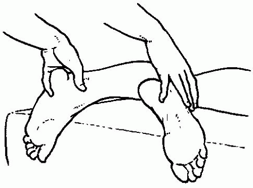
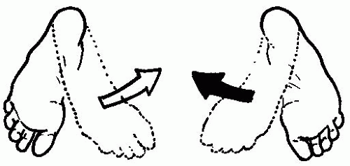
Supine Exam With the child in the supine position, the doctor checks for hip adduction, abduction, and leg balance. In this position the posture of the arms can be checked, as well as whether the posture is contracted or relaxed. For acetabular restriction, the doctor grasps the infants’ ankles and feet then rotates the feet medially while observing for limited ROM (Fig. 28-15). The feet should medially rotate internally equally.


FIGURE 28-16 Psoas check.


FIGURE 28-17 Acetabular restriction on the right.

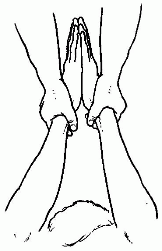
The psoas also can be checked in the supine position; the clinician grasps the child’s hands at the wrists, bringing the child’s arms over the his or her head and gently tractioning the arms toward the doctor. The palms are brought together and any discrepancy is noted. If there is an imbalance in this measurement, the side that appears shorter is the side of the contracted psoas (Fig. 28-16). A positive psoas check requires correction to balance the pelvis and the diaphragmatic and pelvic transverse fascial planes.

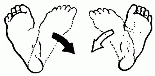
Prone Exam With the infant in the prone position, the clinician can grasp the infant’s ankles and feet and rotate the toes medially (Fig. 28-17). Normally, both feet should medially rotate equally. While the infant is in this position, the doctor can flex the infant’s heels toward his or her buttocks. Both heels should be able to touch the buttocks, and the side that is most restricted is the putative side of sacrum anteriority.


CERVICAL SPINE ADJUSTMENTS


Inverted Swing Adjustment

The infant is held with one hand by the shins or thighs, depending on the size of the child, while the clinician supports the occiput with his or her other hand (Fig. 28-18). If the child is too large to hold with one hand, grasp the shins or thighs with both hands. Slowly tip the infant upside down and observe. A normal child hangs relaxed. If the child laterally bends or rotates his or her head a cervical subluxation may be indicated. Holding the child upside down for 10 to 15 seconds may possibly assist the cervical spine to self correct. The doctor can swing the child back and forth gently to assist the correction. This procedure may be done up to three times with a 10-second interval
between each. If this fails to correct the subluxation(s), then specific adjusting techniques are necessary (For contraindications see “Inverted Swing Test” earlier).


FIGURE 28-18 Inverted swing adjustment.


Atlas Occipital Adjustment (C1-C0)

Placing one hand under the occiput with the middle and ring fingers 1 in. apart and pointing toward the occipital condyles, the clinician’s opposite hand straddles the sphenofrontal region and monitors the area for movement (Fig. 28-19). The cervical tissues (at the condyles) then soften. Then the doctor slightly pulls the occiput away from the atlas (posterior) as the other hand brings the sphenofrontal area anterior and inferior (toward the nose). As the occiput moves posterior, the clinician spreads the middle and ring fingers of the occipital contact hand slightly apart.


FIGURE 28-19 Atlas-occipital set-up.


FIGURE 28-20 Occipital-atlanto restriction.


Occipital Atlanto Restriction (C0-C1)

This technique is used for lateral flexion or flexion and extension of the occiput on the atlas. The doctor can perform the direct or indirect method. The doctor places bilaterally the index and middle fingers to the right and left occipital bowls, slightly lateral to the occipital condyles, with the thumbs placed gently to the right and left frontal areas approximately ½ in. lateral to the metopic suture (Fig. 28-20). For the direct method the doctor side bends the skull gently (do not involve the cervical spine) into restriction and holds the contact until the tissue releases and ROM on both sides is equal.

For the indirect method the doctor engages natural occipital flexion on the side that has a greater ROM without cervical spine movement, then holds the position until the tissue relaxes. Once the tissue relaxes, the clinician gently and quickly moves the occiput into the direction of restriction.


FIGURE 28-21 Atlas condyle adjustment.


Atlas Condyle Adjustment/Posterior Superior Occiput (C1-C0)

This technique is used when tension is found on the high occiput side with restricted ROM, especially during side bending or lateral flexion.

The clinician places his or her index finger under the posterior superior occiput and stabilizes the temporal and occipital bones on the opposite side with the other hand. Then the doctor rotates the contact index finger on the posterior superior occiput side inferior and medial until the tissue relaxes; at the same time, the opposite hand is guiding the skull on the other side slightly lateral and superior. Once the limit of range of motion has been reached the doctor makes a slight impulse adjustment with the index finger (Fig. 28-21).


Indirect Technique (Modified Ortho-Bionomy)

The cervical stairstep technique is used to determine the vertebral level to be adjusted. The clinician palpates for swollen, tight muscle nodulations at the desired vertebral levels with positive stairstep indicators. When a nodule is detected the clinician can press slightly posterior to anterior on both the nodulated side and the opposite side of the spine in a reciprocating pattern. If a restricted ROM is found on either side, then the adjustment of that vertebral level is indicated. The contact is made on the swollen, tender nodule with the index finger (Fig. 28-22). Each region of the cervical spine calls for a slight difference in corrective procedures.

The cervical spine is divided into three areas: upper cervical (C1 and C2 axis), midcervical (C3-C5), lower cervical (C6-C7 and occasionally T1). The atlas and axis contact points usually are found on the posterior arch, lateral mass, or transverse process of the atlas and the lamina pedicle junction or the transverse process of the axis. Both of the clinician’s hands support the patient’s head as he or she gently lifts the head and shifts it laterally, away from contact point (i.e., if contact is on the right, move the head to the left). The clinician should not rotate or bend the head to the side. The head is maintained in a side-shifted position as a light pressure is applied on the contact point while gently curving the neck and head around the contact by rotating, side-bending, and extending the head. The doctor should then gently compress the neck into the contact point and hold for 10 to 60 seconds until a release of tension is felt at the contact point or the older child patient reports a 50% or better reduction in discomfort at the point. The head is then returned to a neutral position and indicators are rechecked.


FIGURE 28-22 Indirect technique.

For C3-C5, the contact point of the involved vertebra is usually on the lamina pedicle junction or transverse process and is held with the middle or index finger (Fig. 28-23). A light pressure is maintained on the contact while the other hand slowly rotates and side-bends the neck around the contact until there is maximum softening of the point or 50% pain reduction. Next, the doctor compresses the cervical spine slightly from the top of the patient’s head toward the indicator point, where it is held until tension reduces (5 to 10 seconds). The doctor then returns the head to the neutral position while gently releasing the compression, followed by a recheck of the previous indicators.

To adjust C6-C7 the doctor must first obtain a setup position for a more accurate contact (Fig. 28-24). The clinician makes sure the contact point is directed toward the cervical spine, not the shoulder, and then applies gentle pressure medially. The opposite hand slowly rotates the patient’s head away from the contact point. The movement should not be forced; rather, the head is allowed to roll to the side opposite the contact.

The doctor maintains the contact and light compression down the line of the neck while slowly curving the patient’s neck and head back around the point
(the rotation of the head can be lessened slightly). The head and contact point are held in the positions that maximize softening of the tissues. The doctor compresses down the line of the neck toward the contact and holds pressure for 10 to 60 seconds and then returns the head to neutral while gently releasing compression.


FIGURE 28-23 Indirect technique, C3-C5.


FIGURE 28-24 Indirect technique, C6-C7.

It is important to note that, for maximum correction, the doctor can make more than one contact in each area of the cervical spine. If the tissue at the contact point begins to stiffen, the doctor has probably passed the best release position and should begin the procedure again.


Double Thumb Thrust

This technique is used mainly when the atlas or axis exhibits a large degree of laterality or the major subluxation is on the side of anteriority. The infant is in the supine position and the head is rotated so that the side of laterality is facing the ceiling. The contact is the tip of the doctor’s thumb on the transverse process of the atlas or axis, and the other thumb is placed over the nail of the contact thumb (Fig. 28-25). The line of drive is lateral to medial, with a slight anterior to posterior or posterior to anterior correction if rotation is involved.


FIGURE 28-25 Double thumb thrust supine, C1-C2.


FIGURE 28-26 Double thumb thrust prone, C1-C2.

The adjustment is performed by a quick thrust, created by rapidly contracting the triceps muscle as the doctor brings his or her arms toward each other using the elbows as a focal point. There is no recoil in this adjustment. Rapid acceleration is the major factor in accomplishing the correction. This technique also can be performed with the patient in the prone position, which may be more effective when laterality is the major component.

The infant is placed into the prone position and the head is rotated so that the side of laterality is facing the ceiling. The contact is the tip of the thumb on the transverse process of the atlas or axis; the other thumb is placed over the nail of the contact thumb (Fig. 28-26). The line of drive is lateral to medial, with a slight anterior to posterior or posterior to anterior correction if rotation is involved.


THORACIC SPINE ADJUSTMENT


Trapezius Fiber Correction

After palpating the trapezius fibers, the doctor must determine both the active fiber and the associated vertebra. The active trapezius fiber will feel tight and swollen and is usually tender to the touch in relation to the other fibers. Once an active fiber is found, the clinician palpates to the lateral aspect of the tip of the corresponding vertebra, based on the trapezius fiber chart (Table 28.1). If pain sensitivity is too unreliable, then look for the spinous process that is positioned directly inferior to the one above and below. The most tender or inferiorly tipped (extended) corresponding vertebra should be the one that is adjusted. When the correction is made the clinician returns to the trapezius fiber. Swelling, tightness, and sensitivity should be
reduced at least 50%. If two active fibers are discovered in a row, there is probably a set of anterior displaced vertebrae that need to be addressed. The line of drive for the correction of a trapezius fiber subluxated vertebra is straight inferior to superior with no Y-axis rotation. (Fig. 28.27).


FIGURE 28-27 Trapezius fiber adjustment.


Occipital Fiber Correction

As noted earlier, there are three occipital lines on the occiput. For the purposes of this chapter the author will only discuss the corrective procedures for lines 1 and 2. After palpating the occipital fibers, the doctor determines first the active fiber and whether it is a line 1 or line 2 fiber (Table 28.3). Both fibers will be tender and slightly swollen, but the line 1 fiber will be taut and tender whereas the line 2 fiber will be more swollen or puffy. It should be noted that one cannot have a true (Fig. 28.28). line 2 fiber unless there is a line 1 fiber directly above it. Occipital fiber line 1 subluxation may be indicative of a vasomotor subluxation, usually in the thoracic and lumbar spine. There are structural, meningeal, and vascular components to this subluxation. Its position is one of inferior tippage of the involved vertebra, and the line of drive of the correction is straight inferior to superior without rotation. The subluxated vertebra is determined by correlating the active occipital fiber with the corresponding vertebra from the occipital fiber chart (Table 28.3). Similar to determining the subluxated vertebra in the trapezius fiber evaluation, the doctor is looking for the spinous process that has the most inferior tippage. Once the vertebra is determined, the doctor contacts the spinous process with his or her thumb or index finger; at the same time the doctor contacts the lamina of the corresponding cervical vertebrae with the thumb and index finger of his or her other hand. The doctor then gently pumps the spinous process in an inferior-superior direction until heat or moisture is felt at the cervical contact. This is a sympathetic response and is necessary to reduce all aspects of the subluxation. Once the response is noted a thrust is delivered in an inferior-superior direction with a nail point, double thumb, or double transverse contact on the thoracic or lumbar vertebra moving the spinous inferior to superior.


TABLE 28.3


Occipital Fiber Chart


Occipital line


1


2


3


4


5


6


7


Cervical


1


2


3


4


5


6


7


Thoracic


1,2,10


3,11,12


4,5


6


7


8


9


Lumbar


1


2


3


4


5


Occipital line 2


1


2


3


4


5


6


7


Thoracic


1,2,10


3,11,12


4,5


6


7


8


9


Lumbar


1


2


3


4


5


Sacrum


1


2


4


FIGURE 28-28 Occipital fiber adjustment.

Occipital fiber line 2 possibly is indicative of a viscerosomatic subluxation in which the offending vertebra assumes a rotational subluxation pattern that also affects the dural port, causing swelling and inflammation, usually on one side. The vertebra in question will palpate as a rotational subluxation with a high transverse process on one side. Once the active occipital fiber is discovered, the doctor maintains contact on the involved occipital fiber while palpating the corresponding vertebra from the occipital fiber chart his or her other hand. Once the subluxated vertebra is determined, the doctor places his or her index finger or thumb over the high transverse process. Then, the occipital fiber is manipulated in a circular motion while the index finger maintains a steady pressure over the involved transverse process. The tension and swelling will begin to dissipate at the occipital
fiber, the transverse process, or both. When this tension is reduced by 50%, the doctor should thrust straight posterior to anterior over the high transverse process to theoretically set the subluxated vertebra.


FIGURE 28-29 One finger tap.

May 24, 2016 | Posted by in PEDIATRICS | Comments Off on Sacro-Occipital Technique for the Pediatric Patient

Full access? Get Clinical Tree

Get Clinical Tree app for offline access