Fig. 4.1
PNE components. (a) Prep kit which includes drapes and prepping materials. (b) Test stimulation kit: foramen needles, syringe, and needle for local anesthetic, test stimulation lead, marking pen, hemostat, and forceps
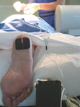
Fig. 4.2
The grounding pad is attached to the patient’s foot with the red connector of the Test Stimulation Cable attached. The black connector of the Test Stimulation Cable is attached to the Patient Cable and the Test Stimulation Cable is attached to the test stimulation box as shown
Selecting the Appropriate Foramen Using Fluoroscopy
S3 is the ideal target for lead placement and we attempt to place bilateral leads at this level during the PNE. Rarely, S4 is adequate or preferable, but S2 is not appropriate for chronic stimulation due to the activation of lower extremity motor efferents. Fluoroscopy is used to visualize the sacrum in an anteroposterior (AP) view to identify the medial edge of the sacral foramen on one side, which is marked on the skin with a marking pen (Fig. 4.3a, b). The contralateral foramen location can be approximated by moving two fingerbreadths over and once verified with fluoroscopy, the skin is marked. The skin may be marked or one can visualize an imaginary vertical line parallel to the spine at the medial edge of the foramen to help stay lined up when accessing the foramen from a superior point on the skin. A cross-table fluoroscopic view is then obtained to locate the S3 foramen laterally. Only a few minutes total is spent using the AP projection, with the major portion of the procedure performed in the lateral view. S2 is readily identified as the point where the sacroiliac joint fuses, forming a characteristic shadow. The first anterior protrusion or “hillock” from the anterior surface of the sacrum below this shadow is typically S3. In order to determine the skin entry point of the foramen needle, the skin is marked with a hemostat while looking at skin surface and the sacrum together in a lateral plane (Fig. 4.4). The point of entry is found along the line marking the medial edge of the sacral foramen (previously made while in the AP view), with a line drawn in the mind’s eye starting at the skin mark, paralleling the fusion plain between the sacral vertebra, and targeting a point approximately 1 cm above the S3 hillock. This line is in a cephalocaudal direction at an approximately 60-degree angle. The use of fluoroscopy allows the correct angle to be determined for any body habitus.
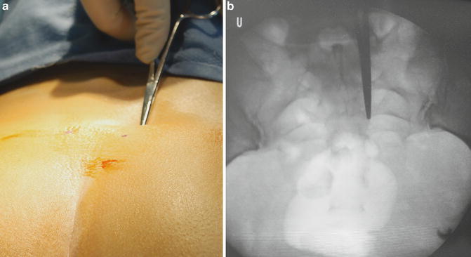
Fig. 4.3
Identifying the medial edge of the sacral foramina using fluoroscopy with (a) showing the clamp on the patient’s skin and (b) showing the AP X-ray
Positioning the Needle in the S3 Foramen and Placement of the Temporary Lead
The location of the needle entry point on the skin should be anesthetized with 0.25 % bupivacaine, 1 % lidocaine, or a combination to create a dime-sized wheal. The subcutaneous tissue does not need to be infiltrated with the local anesthetic but the sacral periosteum may require some of the anesthetic if the patient experiences discomfort as the foramen needle touches the bone. Once the bone is touched, a spot lateral fluoroscopy view is obtained to determine if the insertion point is correct, and whether the needle must be aimed in more cephalic or caudal angle. Once the orientation is correct, the needle is “walked” up or down along the line of the medial edge of the foramina until the needle drops off into the foramen (Fig. 4.5). It is important to pull the needle back before changing positions while trying to locate the foramen to avoid torqueing or bending the needle. For larger patients, a 5 in. needle is available. We typically refer to this as “the other” needle in order to minimize patient anxiety.
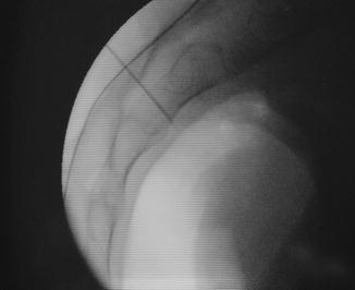
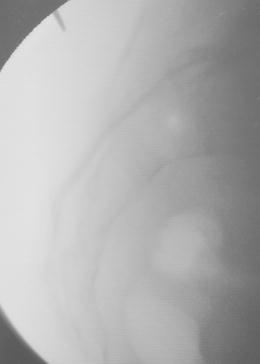
Fig. 4.5
Foramen needle placed superior to the hillock of S3
Since the patient is not sedated during the PNE, it can cause discomfort to reposition the needle during the procedure, and we often will keep the initial foramen placement if responses are consistent with positioning along S3. During placement of the tined chronic lead, one should re-direct the foramen needle as needed to get the best positioning along the course of the S3 nerve root. The needle is then stimulated using the patient cable that is attached to the test stimulation device and the patient is observed for sacral root responses (Table 4.1). Responses that correspond to simulation of S3 are bellows (levator contraction resulting in rolling inward and deepening of the intergluteal fold), dorsiflexion of the ipsilateral great toe, and sensation of the stimulation in the genital, perineal, or anal region.
Table 4.1
Sacral root responses
Sacral level | Motor response | Sensory response |
|---|---|---|
S2 | Bellows, clamp, dorsiflexion foot, heel rotation, calf cramping | Genital |
S3 | Bellows, dorsiflexion great toe, dorsiflexion foot | Genital, perineal, anal |
S4 | Bellows | Anal |
If responses are not consistent with S3 and the patient will tolerate further needle manipulation, the skin entry point is re-approximated using lateral fluoroscopy to aim for the next foramen, either above or below the initial point of stimulation. Once appropriate responses are elicited confirming position in S3, the needle stylet is removed and the Test Stimulation Lead (Medtronic) is passed through the needle to the marking on the lead that corresponds to the needle size used (3 or 5 in.). A fluoroscopic image is obtained to gauge the depth of the lead. It is better to err on being slightly deeper rather than too shallow as the lead will likely migrate during the testing period. The foramen needle is removed along with the lead, while maintaining its depth and keeping the stylet in place, and then it is stimulated to assess responses. The PNE lead can be pulled back under fluoroscopy and/or while being stimulated, to gain better positioning. Finally, the lead stylet is removed leaving only the test lead in place. The procedure is then repeated on the contralateral side.
To decrease the potential for lead migration during the testing phase, the author prefers to tunnel the leads using a spinal needle (Fig. 4.6a, b). The leads are then secured in place using a gauze and Tegaderm dressing. Lastly, the leads are attached to Test Stimulation Cables, which are in turn attached to the external stimulation device during sub-chronic stimulation. Patients are then instructed on device use and will complete voiding diaries during a 3–10 day length of trial to evaluate the therapy. During the testing period, they will trial both leads individually. At the end of the trial period, the leads are extracted in the office by removing the dressing and simply pulling gently on each lead. Success is determined through comparing the voiding diary obtained during test stimulation to the baseline diaries, and also by asking the patient subjectively how they feel their symptoms were managed during the trial. If trial is successful, defined as >50 % improvement in symptoms, the patient is offered implantation with placement of the tined lead and INS during a single procedure. If therapy did not result in at least a 50 % improvement in symptoms, the patient can choose to undergo a staged trial, especially if there were any concerns regarding lead migration or lead placement that may have affected the outcome.
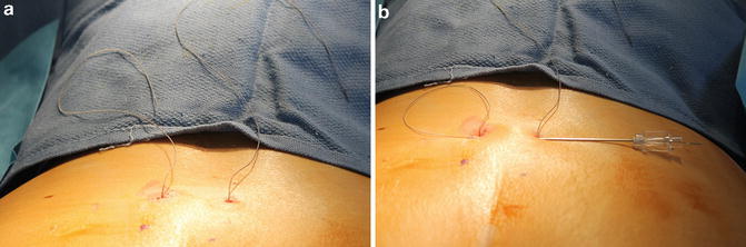
Fig. 4.6
(a) PNE leads after placement. (b) Tunneling of the leads to decrease migration during the trial
Staged Lead Implantation as Initial Trial
Patient Positioning and Preparation
A staged trial involves placement of the tined quadripolar lead connected to a lead extension that is externalized for a prolonged test stimulation trial. As with the PNE and discussed above, the patient must complete a baseline voiding diary prior to the procedure. The procedure is performed with a combination of conscious sedation or MAC with local anesthesia and therefore the patient does require medical clearance to undergo anesthesia. It is preferable to perform the procedure under MAC rather than general anesthesia to allow the patient to give sensory feedback during lead placement. On rare occasion, a patient is not an appropriate candidate for MAC based on other comorbidities and requires general anesthesia. It is important in these situations that the surgeon has good communication with the anesthesia team about the medications given as only a short-acting paralyzing agent should be used to avoid blocking pelvic floor muscle responses during intraoperative stimulation. A preoperative dose of an antibiotic with coverage against skin flora such as cephazolin (Ancef) or vancomycin, if there is concern for MRSA, is administered prior to the procedure. A Hibiclens wash the night before, and morning of surgery, and pre-op skin wipe down with a sage cloth are also measures, which may reduce the potential for infection.
The patient is placed in prone position on a table that will accommodate fluoroscopy with the hips positioned on the table where the c-arm unit will pass beneath the table allowing the surgeon to view the sacrum on both AP and lateral views. Two chest rolls are placed to assist with respiration and pillows are placed under the hips and shins to pad pressure points. The feet remain uncovered to allow observation of motor responses during intraoperative stimulation. The lower back and buttocks are first wiped with alcohol, and then, after drying, prepped with an antiseptic solution such as Dura Prep (3M) solution. After the prepping solution has dried, towels are placed at the bottom of the buttocks, on the sides lateral to where an INS would be positioned, and above the estimated location of L5–S1. An Ioban sheet (3M) is placed smoothly over the entire remaining area of exposed, prepped skin, and the buttocks are gently pulled apart and then released to allow the Ioban to attach/insert itself into the intergluteal fold. Taping apart of the buttocks is not needed in order to see the bellows response, and is discouraged due to the potential for creating patient anxiety and muscle tension. The components of the lead kit are shown in Fig. 4.7. As with the PNE discussed previously, a grounding pad is placed and Test Stimulation Cable and Patient Cable are connected to the external stimulation device (Fig. 4.2).
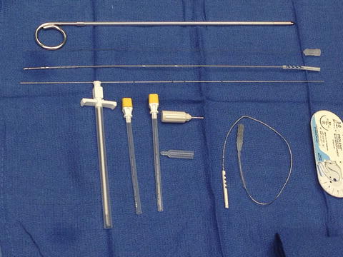
Fig. 4.7
Components of lead introducer and lead kits: tunneling device, straight stylet, lead with ball tip stylet in place, directional wire guide, introducer and sheath, two 3 in. foramen needles, torque wrench, plastic covering/boot, and lead extension wire
Selecting the Appropriate Foramen and Positioning the Needle
The process of using fluoroscopy to identify the medial edge of the S3 foramen and identifying S3 on lateral views is the same as described for the PNE. One difference in placement of the tined lead is that only a single lead is placed rather than performing bilateral placement. Either side can be chosen for placement but if the patient has a lateralizing pain component, it is preferred to place the lead on that side. Identifying the skin entry point, administration of local anesthesia to the skin, and placement of the foramen needle is also the same as the PNE. The foramen needle should follow a cephalocaudal path, paralleling the fusion plane between the sacral vertebrae, passing through the sacrum approximately 1 cm superior to the tip of the hillock. The foramen needle is tested only with the tip just anterior to the anterior surface of the sacrum. It is at this point where the “opening threshold” is measured. As opposed to the PNE, it is vital to reposition the needle as necessary to get the most robust responses. We usually aim for this threshold to be at or below 1 V. If it is higher than 2 V, reorientation of the foramen needle is needed, making sure that it is as medial as possible related to the edge of the bone, and also as high as possible related to the hillock. For example, if the tip of the foramen needle is at or below the hillock just as it enters the pelvis, it is nearly always incorrectly placed, and does not need to be tested before repositioning. Also, it is important to note the order in which motor responses are seen at this point. Bellows should come first, and then toe flexion. An opening threshold at or below 1.5 V, with the appropriate pattern of motor and sensory responses, should be obtained before attempting to deploy the tined lead.
Placement of the Introducer Sheath and the Tined Lead
Once the needle has been positioned, a small skin nick is made alongside the needle making sure the needle moves freely within the small incision. The skin nick must be through the skin into fat, and long enough (0.5–1.0 cm) to allow eventual tined lead placement without causing it to be trapped superficially. The inner stylet of the needle is removed and the directional wire guide is passed to the mark corresponding to the needle length (3 or 5 in.). The foramen needle is removed leaving the directional wire guide in place. The lead introducer sheath is then passed over the directional guide under fluoroscopy until the radiopaque marker present at the tip of the sheath is located approximately 1/2–2/3 through the bone table (Fig. 4.8a, b). This step is emphasized as it is critical to the reproducibly successful positioning of the tined lead. Once the sheath has been placed at the proper depth, the introducer stylet and directional guide are removed.
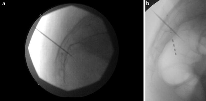
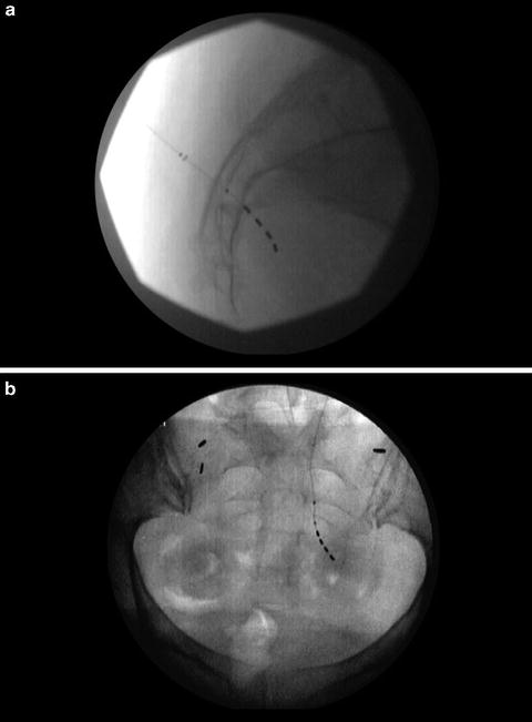
Fig. 4.8
(a) Lead introducer and sheath in place. (b) Lead introducer in place during a lead revision. Note the different angles of entry and position with respect to the S3 hillock
Prior to passing the lead, the authors suggest exchanging the straight and stiffer stylet, the lead comes packaged with, to the ball-tipped (curved) stylet, which is provided in the lead kit. This is because it is softer than the straight stylet, and allows for attachment to the lead. The lead/stylet assembly becomes more flexible and steerable, allowing it to more precisely approximate the course of the sacral nerve as it enters the pelvis. The lead is passed through the introducer under fluoroscopy with care not to deploy the lead. Accidental deployment can be avoided easily by keeping the introducer tip 1/2–2/3 of the way through the bone table, and making sure that contact points 2 and 3 of the tined lead straddle the bone table. The lead has two marks on the upper half of the lead and if the most proximal (upper) marking passes into the sheath, the lead will be deployed as the tines will be located outside of the sheath. The lead should point slightly caudally and laterally (“down and out”) as it passes anterior to the sacrum. When viewing on a lateral X-ray, one can assess for whether the lead curves outward or laterally by looking at the distance between the lead contact points. The distal contact points (0 and 1) will appear to be spaced closer together in the lateral view if the distal lead points away from its initial entry point anterior to the sacrum (Fig. 4.9a, b). On the AP view (usually taken after final deployment) the proximal contact spacing (between points 3 and 2) should appear closer than the distal (1 and 0) since the lead is coming towards and then moving away from the viewer. If the lead is not pointing in a “down and out” position, it should be repositioned by pulling the lead back under fluoroscopy until the distal tip is within the introducer sheath before adjusting/turning and re-advancing to help pass it along a different path, which can be confirmed on fluoroscopy.