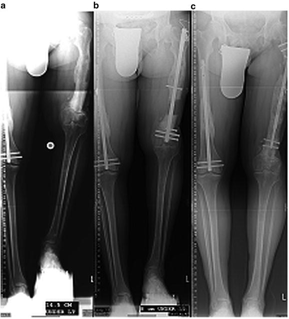
Fig. 9.1
The ISKD was found to be most useful for posttraumatic femoral length discrepancies
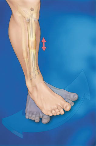
Fig. 9.2
The ISKD and Albizzia nails are activated by manual limb rotation
A new era has begun with the introduction of intramedullary lengthening devices whose distraction is controlled by an external power source which causes an internal actuator to effect the desired amount of distraction. Baumgart and Betz first introduced such a device in 1992 [8]. Baumgart further developed specific insertion tools for the FITBONE nail (Wittenstein Intens, Igersheim, Germany), and published a novel planning method in 2009 [7]. The FITBONE device employs an electric motor imbedded in the telescopic rod, which is activated by intermittent transcutaneous transmission of radiofrequency waves to a subcutaneous receiver that converts these waves into an electrical impulse discharged via a connecting cable (Fig. 9.3). Distraction only occurs when the transducer is placed directly over the receiver, allowing precise control of distraction rate and rhythm. This device has since undergone multiple improvements, and the current generation has been used in over 2,000 cases world-wide. Models suitable for antegrade, trochanteric, and retrograde femoral use are available. A tibial model is in use as well. A bone transport device and a model for short amputation stump lengthening are also available (Fig. 9.4a, b). The FITBONE device requires specific training under the direction of its inventor, Professor Rainer Baumgart or a designee. The FITBONE device is currently available in the USA only under an FDA-approved compassionate use exemption.
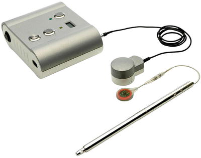
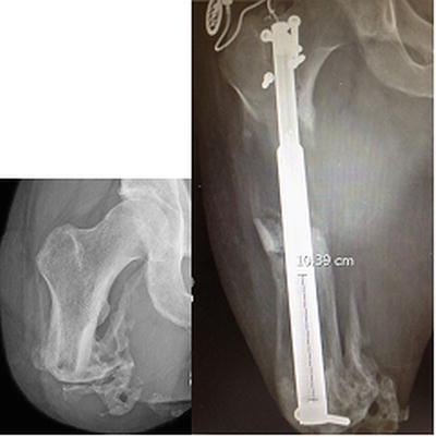
Fig. 9.3
The FITONE nail has an attached cable and antenna. The transformer box shown converts electric current to radiofrequency waves, transmitting energy transcutaneously
Fig. 9.4
(a, b) The FITBONE stump lengthener was used to lengthen a traumatic above knee amputation for a total of 18 cm, allowing the patient to be fitted with prosthesis and walk without assistive devices
The PRECICE nail (Ellipse Technologies, Irvine, CA) was FDA-approved and introduced in 2012. The telescopic nail has a magnetic drive mechanism that is activated by a handheld external electromagnetic controller. Similar to FITBONE, the surgeon instructs the patient in its use, and the device is specifically programmed by the surgeon to prevent application of an improper rate. The patient or family member then performs the distraction by applying the controller directly over the internal magnet in the limb three to four times daily, with the rate and rhythm being adjusted according to weekly clinic visits and radiographs. This device can apply either compression or distraction, does not require a cable/antenna-receiver, and is fully FDA-approved. The manufacturer recommends specific advanced instruction for its users. Either device requires removal after complete corticalization has developed, typically 1–2 years after placement. The PRECICE device has now been used in over 800 cases worldwide (Bart Balkman, Ellipse Technologies, personal communication) (Fig. 9.5).
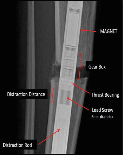
Fig. 9.5
The PRECICE mechanism has a spindled magnet attached to gear boxes which rotate against the distraction rod
General Guidelines for Motorized Intramedullary Limb Lengthening
As with all limb lengthening procedures, appropriate surgeon education is essential. The properly educated surgeon then organizes a dedicated team of nurses, therapists, and orthotists to ensure the comprehensive care of these patients who often have complex medical and psychosocial issues.
Preoperative studies include a standing film of both lower extremities with block leveling of the pelvis. Foot height differences are considered to be part of the tibial discrepancy. A standing lateral film of the femur or tibia is necessary, inspecting for obvious angulation as well as the more subtle variation in the canal thickness often observed in longstanding deformities. All X-rays are made with a magnification marker so that the segment length and canal diameter can be accurately measured.
The Reverse Planning Method
The Reverse Planning Method described by Baumgart begins with defining the final ideal correction accounting for length, angulation, and translation [7]. This method can be used with any approach to the femur or tibia, but is particularly necessary for femoral lengthening, as intramedullary lengthening along the anatomic axis of the femur will cause medial translation of the knee and lateralization of the mechanical load to the knee. This coronal plane translation has been estimated at 1 mm per centimeter of lengthening, but depends on the magnitude of the preoperative deformity, the location of the corticotomy, the neck-shaft angle, and the length to be achieved [23]. Deformity correction with an intramedullary nail must then occur acutely intraoperatively, anticipating the future position of the knee. Intramedullary lengthening of the tibia does not typically lead to similar translation problems since the tibial anatomic axis normally approximates its mechanical axis.
It is important to execute the following steps with precision in the preoperative planning process (Fig. 9.6a–g).
Fig. 9.6
(a–g) Reverse Planning Method for retrograde nailing of the femur
Step 0
Make a full-size tracing of the radiograph of the entire lower limb, marking reference points, angles, and lines. Once the bone to be corrected and lengthened is determined by the malalignment test [24], consider its curvature in both the coronal and sagittal planes. If a straight track for the nail cannot be achieved, an alternate corticotomy site or a second osteotomy should be considered. If the medial proximal tibial angle (MPTA) is normal (85–90°), continue the tibial mechanical axis line to a point well above the current femoral head location (see Fig. 9.6a).
Step 1
Draw and extend the mechanical axis of the tibia proximally with sufficient length to account for the lengthening goal (see Fig. 9.6b).
Step 2
Draw the location of the femoral head in its final position after lengthening along the mechanical axis has occurred (see Fig. 9.6c). Choose a corticotomy level near the deformity apex, but of sufficient distance from the knee joint to allow for both locking and blocking screw insertion (generally 7–10 cm from the knee joint line). Depending on the severity of the deformity and the magnitude of the planned lengthening, selection of a corticotomy site too distant from the knee may result in excess cortical reaming and undesirable conditions for healing.
Step 3
A second tracing is made outlining the proximal femur to the level of the corticotomy (see Fig. 9.6d). The anatomic axis is then defined and drawn, and the nail is outlined to scale. In this step, the surgeon must consider the effect of reaming in both planes, being certain that cortical integrity is maintained to accommodate the size of implant and characteristics of the bone.
Step 4
After overlapping the second tracing on the first, and placing the femoral head in its future location, the papers are then swiveled until the anatomic axis lines are matched. The nail tracing should enter the distal fragment in a position of anatomic harmony, and the mechanical lateral distal femoral angle (LDFAm) should approximate 90° (see Fig. 9.6e).
Step 5
Shift the outline of the second drawing distally along the anatomic axis line to the point where contact is made between the corticotomy ends (see Fig. 9.6f). This image of the bone segment and nail position, including angulation and translation, now becomes the intraoperative goal (see Fig. 9.6g). It will replicate the desired intraoperative position with regard to sagittal translation and angulation, and should allow the exact nail position to be duplicated. If coronal deformity exists, the corticomy can be manipulated directly with an osteotome and/or indirectly with Shanz pins and sterile bumps.
Visual Aids
Creating visual aids for surgery can be helpful in many ways. The preoperative plan, printed full size, is secured to the surgical suite wall, next to the patient radiographs. Skin markings are then created. The fluoroscope is brought into the field in the AP projection. The hip, knee, and ankle reference points and lines are marked on the overlying skin with a sterile marking pen. The anatomic and mechanical axes are marked on the bone to be treated. The patella and infrapatellar ligament are marked since they are used to maintain consistent AP positioning. The proposed corticotomy site is marked (Fig. 9.7).
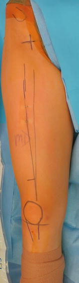
Fig. 9.7
Sterile markings are made on the surface of the skin to aid canal preparation
The selected nail is opened and the proximal, distal, and telescopic portions are indicated with skin clips to identify the desired reaming depth. Anatomic hazards to be avoided, such as growth plates, are also marked. These marks are then used for visually referencing Shanz pin insertion and reaming paths, and for assisting the surgeon in reducing X-ray exposure (Fig. 9.8).
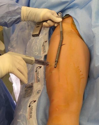
Fig. 9.8
Reaming depth can be guided by applying skin clips at the appropriate levels
Venting the Canal
Reaming a closed long bone causes elevation of intramedullary pressure and intravasation of marrow contents, with the potential for creation of fat embolism. This complication is best avoided by venting the canal to decrease the marrow pressure [25]. The planned corticotomy site is routinely selected as the venting site. This site is drilled (vented) in percutaneous or open fashion using a subperiosteal approach prior to instrumenting the canal. A series of 4–5 mm drill holes allow intramedullary reamings to spill at the corticotomy site, also adding biological support to the lengthening site (Fig. 9.9a, b).
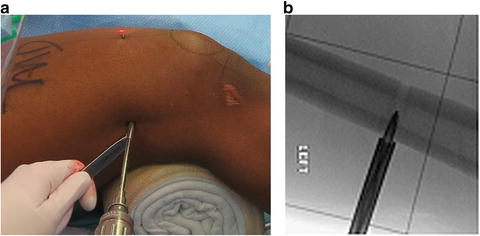
Fig. 9.9
(a) Venting the canal at the level of the future corticotomy is done with a series of drill holes, thus creating a subperiosteal pocket into which reamings will spill. (b) A 5-mm drill bit with sleeve serves this purpose
The actual corticotomy will be performed at a later point in time after the canal preparation.
Shanz Pins
Shanz pins are inserted with c-arm guidance in the lateral position. The femoral condyles are rotated so as to overlap each other on a lateral view, and the pin is inserted from lateral to medial, just inside the posterior cortex at the junction of the metaphysis and epiphysis, and out of the way of the future passage of the nail (Fig. 9.10).
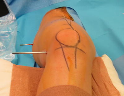
Fig. 9.10
The knee joint skin mark assists parallel Shanz pin insertion without switching c-arm position. The proximal pin is placed rotationally parallel to the distal pin, at the level of the lesser trochanter, perpendicular to the shaft, and posterior to the future nail path
Entry Points
Ideal entry points are required for proper intramedullary nailing and are defined by several authors [26, 27] (Fig. 9.11a, b).
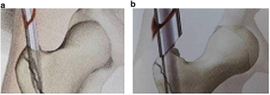
Fig. 9.11
(a) Trochanteric entry is at the medial-most tip of the trochanter. (b) Reaming sleeves protect soft tissue
The correct starting point for trochanteric entry is actually on the further-most point medial on the tip of the trochanter without entering the piriformis fossa.
Reaming Techniques
As the telescopic nails are straight and the canal is not, one must either over-ream a curved canal to accommodate the straight nail, or ‘fit’ rigid reaming to match the straight nail. After the canal has been vented and the Shanz pins placed, reaming can proceed with attention to appropriate entry points suitable to the approach chosen [26, 27].
Conventional Reaming
The canal is first vented. A bulb tipped guide wire is placed. Flexible reamers prepare a cylindrical path but curve at multiple apices, thus requiring over-reaming of 2 mm to accommodate a straight nail. Corticotomy is generally performed after this “over-reaming” with flexible reamers.
Rigid Reaming
The canal is first vented. Canal preparation with rigid reamers creates a well-defined pathway for the straight nail with a future line-to-line fit. Blunt or sharp rigid reamers can shape curved canals with asymmetric wall thickness to accept the nail (Fig. 9.12a, b).
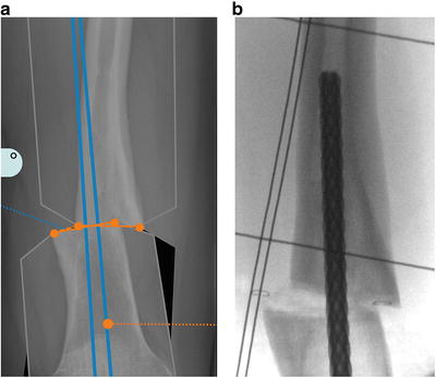
Fig. 9.12
(a) Carefully inspecting the canal preoperatively determines if the canal will accept an intramedullary nail. (b) In specific instances rigid reamers may be used to “shape” the inner canal
Reaming sleeves passed over insertion dilators protect soft tissues from the reamer blades and prevent spillage of marrow contents into the joint or soft tissues.
Rigid reamers are inserted within the tubes along the planned pathway, and are increased in 0.5 mm increments to 0.5 mm greater than the nail diameter. After canal preparation on the “near side” of the corticotomy, the corticotomy is completed with an osteotome and the deformity is corrected to match the plan in step 5. With the plan achieved, reaming then proceeds on the “far side” of the corticotomy to the 0.5 mm greater than the nail diameter.
Regardless of reaming technique, the nail is inserted with simple hand pressure, reaming slightly more as necessary to avoid mallet use, and potential damage to the micromotor. Alignment is checked, the corticotomy is compressed, and locking screws are inserted.
Blocking Screws
Blocking screws (Poller) are known to be useful in trauma and reconstruction applications of intramedullary fixation for correcting and preventing deformity [28, 29]. They function to narrow a canal in epiphyseal and metaphyseal areas, and thus guide nails in juxtaarticular applications (Fig. 9.13 a–c).
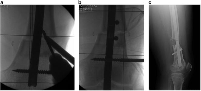
Fig. 9.13
(a) Blocking screws are placed against the nail. (b) Blocking screw location is specific to each case, generally on the “concave” side of potential deformity. (c) A single posterior screw maintained this extension osteotomy
We have learned from our bone lengthening experiences that deformities developing during lengthening are a common event. Asymmetric muscle forces imposed by unequal muscle mass, muscle anatomy, and two-joint muscles create the predictable deformities of varus-procurvatum during femoral lengthening and valgus-procurvatum during tibial lengthening. The development of such deformities can be corrected by adjustments of the fixator in the outpatient clinic when lengthening with circular external fixation. When lengthening with intramedullary techniques, these deformities must be anticipated and prevented with the appropriate use of blocking screws, as later correction requires additional surgery.
Box 9.1. General Guidelines Summary
1.
Blocking screws should be employed to prevent deformity at insertion or during lengthening. They are less likely needed if the deformity and corticotomy apex is at the isthmus, and/or the lengthening is small, less than 3 cm.
2.
Blocking screws are most commonly needed in the distal femur and proximal tibia, as these locations often have large canal-to-nail size ratios.
3.
Postoperative monitoring is done weekly during distraction and monthly during consolidation.
4.
Preoperatively plan each case with life-size drawings or computer graphic simulation. The Reverse Planning Method is most useful in retrograde femoral applications.
5.
Nail length is planned to allow 6–7 cm of the wider portion of the nail in the distracted segment at the completion of distraction.
6.
The canal must be vented before reaming.
7.
Isthmic bone diameter must be able to accommodate reaming 2 mm greater than the nail diameter for flexible reaming, and 0.5 mm for rigid reaming.
8.
Shanz pins control segments and prevent rotational deformity, particularly in femoral lengthenings where the corticotomy is not well visualized through the wound.
9.
Periosteum-sparring, non-heat-generating corticotomy should be positioned at or near apex of the deformity.
10.
Comminution of the osteotomy should be avoided, as this creates nail instability, may prevent acute correction, encourages lengthening deformity, and may lead to poor bone regenerate.
11.
The nail should be advanced by hand pressure only in order to avoid damage of the distraction motor and gear boxes.
Antegrade Femoral Lengthening
Patient Indications
Antegrade femoral lengthening is indicated for patients with leg length discrepancy originating from the femur. Angular and rotational deformity of the proximal to mid femur can be corrected acutely, with the latency period suitably delayed to account for the correction magnitude. A piriformis entry can be used for adults. A trochanteric entry has been shown to be safe for preadolescents as young as age 12 years [30] (Fig. 9.14a, b).
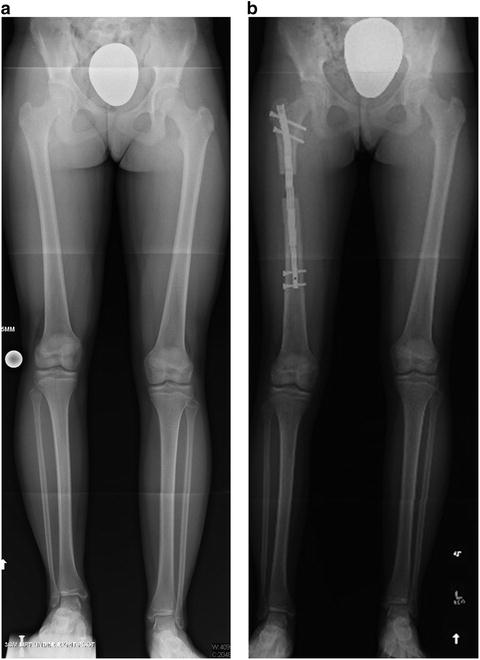
Fig. 9.14
(a) A 16-year-old girl with a 3.5-cm idiopathic right femoral shortening with preoperative weight bearing line 2 mm medial to the medial spine, suggests an antegrade lengthening will result in lateralization of 3.5 mm. (b) A trochanteric entry best avoids the hip vasculature, and resulted in the predicted and acceptable weight bearing line 1 mm lateral
Lengthening along the anatomic femoral axis will result in 1 mm of knee medialization for every 10 mm lengthened, potentially resulting in an undesirable transfer of load laterally [18]. Assessment of the weight-bearing line on preoperative full-length AP X-rays will be helpful in determining whether this amount of medial translation will be harmful to the knee in the future. Acute deformity correction can be assisted by temporary intraoperative placement of Shanz pins, and progressive deformity during lengthening can be prevented by blocking screws (Fig. 9.15a–c).