Central Venous Cannulation
Jane M. Lavelle
Andrew T. Costarino
Introduction
Central venous cannulation (CVC) involves percutaneous placement of a vascular catheter so that its tip is within the lumen of a major, high-flow vein of the abdomen or thorax. CVC is a crucial skill for any clinician who regularly participates in resuscitation and stabilization of critically ill infants and children in an emergency department (ED).
Placing a catheter into the central circulation became a theoretical possibility once Harvey made the revolutionary discovery of the circulation and function of the heart in 1628. Development of vascular access came as the result of the need to understand the clinical function of the circulation and the need to administer intravenous fluids, blood products, and medications. The first record of central venous catheterization was made in England by Stephen Hales in 1733. As part of his investigation of the circulation, he inserted a glass tube into the jugular vein of a horse to measure the central venous pressure. Later the value of intravenous fluid administration was recognized. In 1833, W. B. O’Shaughnessy described the treatment of cholera victims to replace the lost “neutral saline ingredients” of serum. Intravenous saline solutions were first used to treat shock associated with surgery by Rudolph Matas in 1891. Following the identification of the blood types by Landsteiner in 1901 and the development of a method to prevent coagulation in stored blood in 1914, blood transfusion became another important clinical application of intravenous infusion therapy. By the mid-1900s, intravenous fluids, blood products, and medications were a regular part of clinical practice.
When Seldinger described a practical technique for percutaneous entry to central vessels in 1953, the stage was set for CVC to become a standard therapeutic option. By the late 1960s, CVC use had gained widespread clinical acceptance. Today CVC is performed for a broad range of clinical purposes in adults and children of all ages (1,2). Percutaneous CVC is often employed as an emergency procedure during initial patient stabilization, but it is also used as a definitive procedure for long-term patient management. This chapter reviews percutaneous CVC using the Seldinger method and similar techniques via the femoral, brachial, jugular, and subclavian veins as well as the basilic and median veins of the forearm.
Anatomy and Physiology
General Anatomic Considerations
Major sites for percutaneous cannulation of the central veins include the internal and external jugular veins as well as the brachial, subclavian, and femoral veins. Figure 19.1 shows these vessels and their relation to the abdominal and thoracic vena cava and the heart. While vascular anatomy is similar in all age groups, some subtle and important differences exist, particularly in young infants. General differences, including small body size, tissue softness, and compressibility (particularly of the chest), make the body surface landmarks used in locating deep veins less apparent and more easily distorted in younger patients.
More specific considerations also exist for some of the common CVC sites. For example, in infants less than 1 year of age, anatomic factors make subclavian vein entry less attractive than entry at other sites. In this age group, the subclavian vein arches more superiorly as it courses toward the atrium, resulting in acute angles that may obstruct catheter placement. The subclavian arch takes on the more typical horizontal position within the chest only after 1 year of age. Additionally, in young infants, the notch on the inferior aspect of the first rib, a landmark commonly employed to identify the percutaneous entry site for the subclavian vein, is difficult to identify. Finally, the diameter of the subclavian vein is smaller than that of the
internal jugular vein in this population, and for this reason many clinicians prefer the jugular site (3,4,5,6).
internal jugular vein in this population, and for this reason many clinicians prefer the jugular site (3,4,5,6).
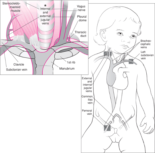 Figure 19.1 Anatomy of the central venous circulation. The shaded areas indicate the preferred sites for cannulation. |
A general anatomic consideration for both children and adults relates to the choice of the internal jugular vein (IJV) or subclavian vein (SV) for catheter placement: these vessels are more easily cannulated on the right side rather than the left. On the right, the IJV assumes a straight course and joins the right SV to form the brachiocephalic (or innominate), which continues on into the superior vena cava (SVC). The left IJV joins the SV at a more acute angle; moreover, the left brachiocephalic forms a sharp angle with the superior vena cava. Adding to the difficulties associated with left side approaches are problems that arise due to the lymphatic communications with these veins. The larger left thoracic duct enters the left SV at its junction with the IJV. The right lymphatic duct is a much smaller structure and frequently is congenitally absent. Finally, the left pleural dome is higher than the right, increasing the likelihood of a pneumothorax during the procedure. Although specific clinical situations such as right-sided neck or chest trauma may preclude use of the right-sided vessels, they are preferred whenever possible (3,4,5,6).
Anatomy of Specific Sites
Femoral Vein
The femoral vein (FV) travels superficially in the anterior thigh, then passes beneath the inguinal ligament, coursing deep into the pelvis to become the external iliac vein. In the proximal thigh (distal to the inguinal ligament), the FV lies within the femoral sheath, where it is medial to the femoral artery, which in turn is medial to the femoral nerve. The mnemonic NAVL (pronounced “navel”) is often used to remember this orientation from lateral to medial: nerve, artery, vein, lymphatic. Thus, the FV can be identified 1 to 2 cm medial to the femoral artery pulse when palpated 1 to 2 cm below the inguinal ligament (4).
Jugular Veins
Internal Jugular Vein
The IJV exits the skull via the jugular foramina and follows a relatively straight course through the neck before emptying into the SV. As mentioned, the right IJV joins the right SV just lateral to the sternoclavicular joint, forming the brachiocephalic (innominate) vein, which continues on in a straight path to the SVC. On the left side, the IJV joins the SV vein at an almost perpendicular angle. Similarly, the left innominate then joins the SVC at a sharp angle (see Fig. 19.1). As the IJV moves caudal in the neck, it becomes more superficial and larger in diameter.
In the cephalad portion of its course on either side of the neck, the IJV is medial to the sternal (medial) head of the sternocleidomastoid muscles. In the midportion of the neck, it is located beneath the line that bisects the angle formed by the sternal and clavicular (lateral) heads of the sternocleidomastoid. In the caudad portion of the neck, it lies just medial to (or sometimes beneath) the clavicular head of the sternocleidomastoid.
Other important structures are in close proximity to the IJV. Within the carotid sheaths, the carotid arteries are medial, posterior and deep to the vein, while the vagus nerve is between the carotid artery and IJV. The cervical sympathetic chain and stellate ganglion are deep and medial to the IJV, and the brachial plexus is found deep to all these structures. The phrenic nerve is lateral and the laryngeal nerve is medial to the carotid-jugular vascular bundle. Lymphatic ducts enter the SV near the junction of the IJV with the SV. The right IJV is preferred for cannulation whenever possible (5,7,8,9) for the reasons mentioned previously.
External Jugular Vein
The external jugular vein (EJV) drains the structures of the exterior of the cranium and the deep face. It begins within the parotid gland at the level of the angle of the mandible and travels obliquely across the sternocleidomastoid muscle from the angle of the mandible to the middle of the clavicle. Below the clavicle at the level of the posterior border of the sternocleidomastoid muscle, the EJV empties into the subclavian vein at virtually a right angle (5,7,8,9).
Subclavian Vein
The SV arises from the axillary vein as it passes over the first rib. It continues superiorly, passing anterior to the scalenus anterior muscle, before descending slightly as it joins the IJV to form the brachiocephalic vein behind the sternoclavicular joint. The brachiocephalic vein then empties into the SVC. The SV lies anterior to the subclavian artery and the brachial plexus; it is separated from these structures by the thin scalenus anterior muscle. Ventral to the scalenus anterior muscle at this point, the thoracic duct crosses to terminate at the junction of the IJV and the SV. As with the IJV, the right-sided SV is preferred for cannulation for the reasons listed previously (6,10).
Veins of the Forearm
The superficial veins of the forearm are increasingly being used to access the central venous system (Fig. 19.2). The basilic vein, which is used most commonly for this purpose, arises from the ulnar (medial) side of the dorsal venous network of the hand. The network drainage then curves around the medial side of the forearm, joining to form the large basilic vein. The cephalic vein arises on the radial (lateral) border of the dorsal venous drainage of the hand. It passes upward anterior to the elbow along the lateral side of the arm and empties into the upper part of the axillary vein. The basilic vein communicates with the cephalic vein via the median cubital vein. Proximal to the elbow, the basilic vein passes more deeply up the medial side of the arm to join the axillary vein. In most cases, advancing a catheter from the superficial veins of the forearm into the SV or SVC requires passage through the basilic vein rather than the cephalic vein, because the cephalic system is usually too tortuous at the upper shoulder and has a narrow and acute junction with the axillary vein and SVC in the anterior chest.
Indications
General Considerations
CVC in children is almost always performed by a physician, usually an emergency medicine specialist, intensivist, anesthesiologist, radiologist, or surgeon. The operator should be skilled in the technique and familiar with the indications, anatomy, and potential complications of the procedure so that the balance of benefit versus risk can be appropriately judged. As shown in Table 19.1, indications for percutaneous CVC include (a) the need to obtain access to the vascular space in patients with circulatory failure when vasoconstriction, vascular depletion, or other factors preclude access via superficial veins; (b) providing a means for placement of other devices such as a Swan-Ganz catheter or transvenous pacemaker; (c) the administration of vasoactive substances,
thrombogenic therapies, or other medications in order to allow more rapid distribution and onset of these therapies; (d) providing a means for safe administration of hypertonic fluids or highly concentrated medications into a large-volume, high-flow body space; (e) assessment of cardiac function and tissue oxygen delivery through central venous pressure measurement and/or mixed venous blood gas measurement; and (f) providing long-term access to the circulation for repeated administration of medications that may injure a peripheral vein or for repeated blood sampling.
thrombogenic therapies, or other medications in order to allow more rapid distribution and onset of these therapies; (d) providing a means for safe administration of hypertonic fluids or highly concentrated medications into a large-volume, high-flow body space; (e) assessment of cardiac function and tissue oxygen delivery through central venous pressure measurement and/or mixed venous blood gas measurement; and (f) providing long-term access to the circulation for repeated administration of medications that may injure a peripheral vein or for repeated blood sampling.
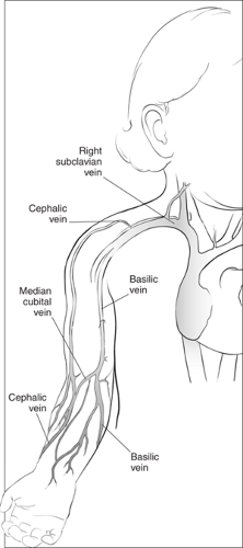 Figure 19.2 Anatomy of the superficial veins of the arm. |
TABLE 19.1 Indications for Central Venous Cannulation | |
|---|---|
|
The only absolute contraindications for this procedure are vascular disease in the involved extremity and congenital or acquired vascular abnormality. Relative contraindications include acute inflammation or injury to the skin over the planned entry site and the presence of a hypercoagulable state or bleeding diathesis. Relative contraindications for specific anatomic sites are described below.
Site-Specific Considerations
Femoral Vein
The femoral site has become the first choice for emergent CVC in children for several reasons. First, access at the femoral site does not interfere with airway management or chest compressions. It also has clearly identifiable anatomic landmarks and can be easily compressed to stop bleeding. Unlike the cervical and thoracic sites, where pneumothorax and other serious acute complications can occur, the femoral site is relatively free of such hazards (4,10,11,12). Relative contraindications for CVC at the femoral site include abnormal vascular status of the lower extremity, congenital malformation of the lower extremity, femoral hernia, abdominal tumor or trauma, abdominal ascites, and anticipated cardiac catheterization.
Jugular Veins
General patient care, movement, and entry site dressing care are less problematic if the catheter is not near an extremity. In addition, an entry site for a central venous cannula near the chest ensures that the tip will lie within the thorax, allowing for accurate central venous pressure measurement should this prove necessary. These are the primary advantages that have made the neck and upper chest entry sites popular for CVC, especially in adult patients.
Internal Jugular Vein
The anatomic landmarks for CVC using the IJV are similar in infants, small children, and adolescents. Compared to the EJV, this site has a much higher rate of success for accessing the central circulation. Compared to the SV, the IJV approach has a lower risk of causing pneumothorax but has a higher risk of inadvertent puncture of the carotid artery or stellate ganglion. The proximity of the IJV to the carotid artery and other
important structures make this site relatively contraindicated in children with a coagulopathy (5).
important structures make this site relatively contraindicated in children with a coagulopathy (5).
External Jugular Vein
The EJV is occasionally used for access to the central circulation but is more commonly used for peripheral access. The primary advantage of this site is that the vessel is located superficially, which reduces the likelihood of pneumothorax, carotid puncture, or injury to the sympathetic chain. The major disadvantage of the EJV is that successful CVC occurs significantly less frequently than with the other sites. Difficulty in passing catheters into the superior vena cava from an EJV entry site is due to the sharp turn made by the vein as it courses under the clavicle and to its virtually perpendicular angle of entry into the SV (5).
Subclavian Vein
The SV is the least common site used for percutaneous CVC in children. As mentioned previously, specific anatomic characteristics of infants and children make this approach disadvantageous, which is the reason the site is usually avoided. The size and softness of the chest and clavicles make the landmarks for CVC at the SV site more difficult to identify, and the curvature of the anterior chest in the infant reduces the space available for entering the vein without puncturing the lung or artery. Skill and experience are required to perform this procedure without complications.
As with jugular venous cannulation, the right-sided SV cannulation is favored over the left due primarily to anatomic considerations. The cupola of the lung, which lies inferior to the junction of the IJV and SV and posterior to the subclavian artery, is higher in relation to these vascular structures on the left side as compared with the right. Additionally, the left thoracic duct is large and may be injured during cannulation. Finally, the acute angle of entry by the left-sided subclavian/ innominate into the SVC places the patient at greater risk for intimal damage and vascular perforation (6).
Veins of the Forearm
The basilic or medial veins of the forearm are the sites commonly chosen for so-called peripherally inserted central catheters (often referred to as “PICC lines”). These catheters enter the skin at a peripheral site and are then advanced through the vessel so that the tip of the catheter lies in a large central vein. The advantages of a PICC include (a) there is a reduced incidence of infection compared with a catheter that directly enters a central vessel, and (b) there is a lower risk of vascular injury, arterial puncture, and other complications (e.g., pneumothorax) during placement. The disadvantages compared with direct central venous placement include (a) limited sites exist that provide for successful entry to the central circulation; (b) PICC lines are smaller caliber and are usually limited to single- or double-lumen catheters; and (c) peripheral entry also means longer catheter length, which, combined with the smaller caliber, greatly increases resistance to flow. Consequently, PICC placement is not the method of choice for rapid volume resuscitation. As mentioned previously, advancing a PICC into the SV or SVC is less likely to be successful via the lateral cephalic system because the vessels are tortuous at the shoulder and have a narrow caliber and acute angle of entry at the junction with the SV in the chest. Other sites of entry in the neck and leg have been used but pose greater difficulty in advancing the catheter to a large central vein. Additionally, as the site of skin entry moves closer to the point of entry of the catheter tip into the central circulation, many of the advantages of the PICC technique are lost, and a more traditional method of CVC often becomes a better choice.
Equipment
As shown in Table 19.2, the equipment necessary for performing CVC can be grouped in four general categories: (a) equipment necessary for establishing an aseptic field and maintenance of sterile technique during the procedure; (b) the various catheters, needles, and wires, along with any other equipment needed for placing, securing, and dressing the catheter; (c) monitoring and other equipment necessary to ensure patient safety during the procedure and after the catheter is in place (see Chapter 5); and (d) medications and other equipment necessary to ensure patient comfort and cooperation during the procedure (see Chapter 33).
Ensuring that all the proper equipment for CVC is available is now relatively easy because of the many commercially produced kits available (e.g., Cooke, Abbott, Arrow, and Viggo-Spectramed) (Fig. 19.3). These kits contain most of the equipment included in the first two categories, including antiseptic solution and drapes. Organizing any additional
desired ancillary equipment into prepackaged trays or packets for performing CVC will also improve efficiency and reduce the likelihood of errors.
desired ancillary equipment into prepackaged trays or packets for performing CVC will also improve efficiency and reduce the likelihood of errors.
TABLE 19.2 Equipment Checklist | |
|---|---|
|
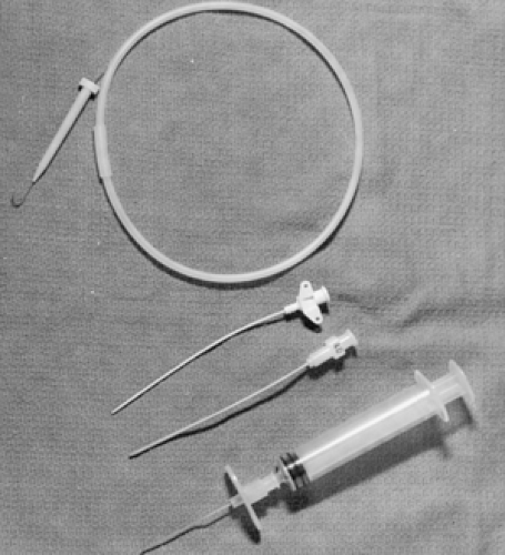 Figure 19.3 Items in a commercially produced pediatric central venous catheter tray (available from various manufacturers). |
Types of Catheters
The two catheter types used most commonly reflect the two most popular methods of percutaneous CVC, one involving passage of the catheter over a guidewire (Seldinger technique) and the other involving passage of the catheter through an introducer (PICC technique). A third type, the “catheter-over-the-needle” system commonly employed for superficial venous access (Fig. 19.4), is often included in central venous access kits. These catheters are sometimes used to begin the process but are not the primary tool for performing CVC.
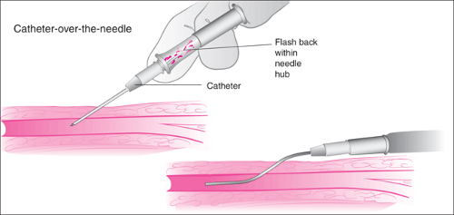 Figure 19.4 Catheter-over-the-needle technique. |
Seldinger Technique
The most popular method for CVC in both children and adults is the Seldinger technique (Fig. 19.5). Described by Sven Ivar Seldinger in 1953 for placement of vascular catheters, this technique has been so successful that its basic principles have now been extended to other procedures, such as emergency tracheostomy placement and nonoperative gastrostomy tube placement. It utilizes a small-gauge entry needle, which punctures the skin and enters the blood vessel lumen. A guidewire is threaded through the entry needle into the blood vessel, and the entry needle is removed while the wire is left in place. A larger-caliber vascular catheter is then advanced over the wire into the blood vessel. The entire procedure may be repeated with increasing sizes of wires and catheters to achieve the desired catheter size, even when starting with a small entry needle.
The guidewires used for the Seldinger technique have both a flexible end and a rigid end. The flexible tip is designed to enter a blood vessel and negotiate its twists and turns while minimizing the likelihood of puncturing the vessel wall. Often the tip is made in a J configuration (Fig. 19.3) and comes with a plastic sleeve used to straighten the J while threading the wire into the entry needle hub. J-wires are particularly useful for situations in which acute angles or sharp turns are encountered within the cannulated blood vessel (see the external jugular
vein approach below). The rigid end of the wire is designed to facilitate threading of the stiff catheter over the guidewire.
vein approach below). The rigid end of the wire is designed to facilitate threading of the stiff catheter over the guidewire.
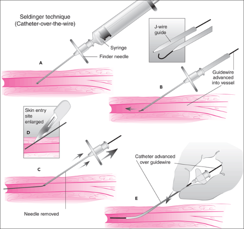 Figure 19.5 Catheter-over-the-wire (Seldinger) technique. A. The central vein is first punctured using a needle and syringe. B. The syringe is removed and the guidewire is inserted through the needle into the vein. C. The needle is removed and the wire is left in place. D. A small incision is made at the entry site to facilitate insertion of the catheter. E. The catheter is inserted over the guidewire and the wire is removed. |
Peripherally Inserted Central Catheter
The introducer technique for inserting a catheter is most commonly employed in the placement of PICC lines. The skin is punctured with a relatively large hollow needle, and after blood return is observed, a catheter is then passed through the needle lumen and advanced into the vein. The needle is removed from the skin once the catheter is in the proper position. In older systems using this technique, the needle remained in place surrounding the catheter, often housed in a plastic shield to prevent it from injuring the patient or cutting the catheter wall (Fig. 19.6). More recently, this technique employs needles that can be peeled apart and completely removed from the catheter (Fig. 19.7). In the various kits for this method, the catheter usually contains a wire stylet that provides added rigidity to facilitate advancement within the lumen of the vein. The stylet is then removed before the catheter is used. In a common variation of this method, a soft, short introducer catheter is first
placed using the Seldinger technique. The styleted catheter is then advanced through the shorter catheter into the central vein. The introducer is usually designed so that it can be removed from the central catheter by peeling it apart.
placed using the Seldinger technique. The styleted catheter is then advanced through the shorter catheter into the central vein. The introducer is usually designed so that it can be removed from the central catheter by peeling it apart.
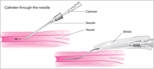 Figure 19.6 Catheter-through-the-needle technique. |
Catheter Plastics
Catheters used today for CVC come in a variety of materials, widths, and lengths as well as with multiple lumens. The first vascular catheters used for infusions or pressure measurement were made of glass, steel, or natural rubber; limitations of these materials significantly restricted the utility and applicability of vascular catheterization in medical care. Over the last 30 years, however, the introduction of synthetic polymers in the manufacture of biomedical devices has been crucial in the development of vascular catheters that are relatively inexpensive, safe, reliable, and effective.
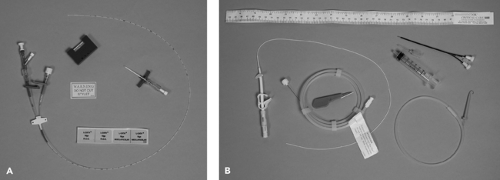 Figure 19.7 A. PICC catheter kit with breakaway butterfly entry catheter. B. PICC catheter kit with soft peel-away catheter initially placed using the Seldinger technique. |
Synthetic polymers used in biomedical devices are high-molecular-weight materials composed of a simple, repeating chemical unit (monomer) (13). The monomers may be linked to one another in chains of linear bonds or may have branched connections forming a three-dimensional network. The material may contain only one type of repeating chemical structure or may be composed of a combination of two or more chemically different copolymers. The most popular material currently used in vascular catheter manufacture is a family of plastics, the polyurethanes, composed of various copolymers. The chemical and physical properties of the monomers and the nature of the polymeric links determine the characteristics of the synthetic polymer, for example, how it changes
in relation to temperature, how it interacts with the blood and other tissues, and whether it is hard or soft, brittle or flexible, etc. In turn, these features determine how suited the materials are for use in the manufacture of vascular catheters and what specific purposes the resulting catheters can be employed for.
in relation to temperature, how it interacts with the blood and other tissues, and whether it is hard or soft, brittle or flexible, etc. In turn, these features determine how suited the materials are for use in the manufacture of vascular catheters and what specific purposes the resulting catheters can be employed for.
Teflon was the first popular material in the manufacture of central venous catheters. Teflon is strong, which allows for a large internal diameter–external diameter ratio and thus maximal lumen size; this also makes the catheter stiff, for improved percutaneous insertion. In addition, Teflon can be made radiopaque because it can be readily mixed with radiocontrast material. The primary disadvantage of Teflon is that catheters made of this material kink easily (14). In addition, although the surface of Teflon is smooth, which reduces thrombus formation in the lumen or at the tip of the catheter, the stiffness of a Teflon catheter can lead to endothelial injury and vascular mural thrombi.
Polyvinylchloride is another plastic used in many biomedical devices, including vascular catheters. Polyvinylchloride has not remained popular for use in long-term vascular catheters for two reasons. First, the material is associated with high thrombogenicity. Although pulmonary artery (Swan-Ganz) catheters are still often made of polyvinylchloride, they are almost always manufactured with a heparin coating to reduce thrombus formation during the relatively short length of time these catheters are designed to be used. The other problem limiting the use of polyvinylchloride for vascular catheters is that drugs infused through these catheters adsorb to the plastic.
Silicone rubber (Silastic) is polymerized polydimethylsiloxane, which confers a flexible rubberlike quality, mixed with silica powder to increase its hardness. Hickman and later Broviac described techniques for providing long-term vascular access using catheters subcutaneously tunneled proximal to their entry into the vein. This remains the primary use of such catheters today. Silicone is smooth and soft, giving catheters made of this material a remarkable record of low infection and clotting rates and a low incidence of injury to vascular and cardiac structures. However, the softness of silicone catheters means that surgical incision and dissection (15,16,17) is needed for placement and predisposes them to fracture or rupture. Kits designed to overcome the need for surgical placement and allow percutaneous placement have been designed, but this technique is not practical for emergency catheter placement. The accuracy of vascular pressure measurements obtained through silicone catheters also has been questioned, although published data do not support this contention (18).
In recent years, catheters made of polyurethane have proven to be the most popular. This is because the various polyurethanes currently available provide the best combination of biocompatibility, stiffness (to ease percutaneous placement), softness and smoothness (to reduce vascular injury, thrombosis, and infectious complications), low tendency to kink, the ability to incorporate radiocontrast, and low manufacturing cost (19).
Catheter Diameter and Flow Characteristics
The diameter of vascular catheters are designated in one of two measurement systems: gauge or French. In the French measurement scale, each unit is equivalent to 0.33 mm in outer diameter (OD). For example, a 5 French catheter has an OD of 1.65 mm. The gauge system developed in a more empiric fashion but is now standardized. The ODs in millimeters for commonly used pediatric catheters are as follows: 14 gauge = 2.1 mm, 16 gauge = 1.6 mm, 18 gauge = 1.3 mm, 20 gauge = 1.1 mm, and 22 gauge = 0.7 mm. Guidelines for the selection of catheters based on age, weight, and height are presented in Tables 19.3 and 19.4.
The French or gauge designations always refer to the OD of the catheter, but with the plastics used in the manufacture of catheters today, one can assume that the luminal diameter is about 40% to 50% of the OD. In multiple-lumen catheters, the equivalent OD is often marked on each lumen port. If all ports are of equal size, a reasonable assumption is to divide the diameter by the number of lumens to estimate the size of each lumen.
Catheter diameter and length have a great impact on medical utility. The appeal of central venous cannulae for the treatment of circulatory failure include the ability to (a) bypass local venous constriction present in hypovolemic states, (b) remain relatively unimpeded by patient movement that might otherwise result in altered infusion rates or loss of access, and (c) avoid extravascular infiltration of fluid. It should be remembered, however, that the necessary length and diameter of these catheters may reduce the infusate flow rate. Factors that determine flow rate through a catheter are expressed in Poiseuille’s law:
where π is the constant Pi, P1 is the hydrostatic pressure driving the fluid into the catheter, P2 is hydrostatic pressure in the blood vessel outside the catheter tip, R is the radius of the catheter lumen, v is the viscosity of the infused fluid, and L is the length of the catheter. Flow therefore increases in proportion to the fourth power of the lumen radius but decreases in proportion to the length of the catheter. In addition, the rate of flow is inversely proportional to the viscosity of the fluid, and so saline and other crystalloid solutions will flow more rapidly than blood products. Increasing the hydrostatic pressure driving the fluid into the catheter will increase the flow rate, whereas high vascular hydrostatic pressure outside the tip of the catheter will reduce the flow rate.
Theoretic considerations determined by Poiseuille’s law can have important clinical implications. For example, when a 16-gauge catheter (1.6 mm OD) is used rather than a 14-gauge catheter (2.1 mm OD) during a resuscitation, the operator should be aware that while the catheter diameter is only reduced by 24%, the rate of flow will be decreased by 66%, assuming all other factors are constant. Similarly, the number of lumens within a catheter must be considered. A 14-gauge double-lumen catheter with one lumen 16 gauge (1.6 mm)
and the other 20 gauge (1.1 mm OD) will have a 66% reduction in flow rate if the 16-gauge lumen is used and a 90% reduction in flow rate if the 20-gauge lumen is used compared with a 14-gauge single-lumen catheter.
and the other 20 gauge (1.1 mm OD) will have a 66% reduction in flow rate if the 16-gauge lumen is used and a 90% reduction in flow rate if the 20-gauge lumen is used compared with a 14-gauge single-lumen catheter.
TABLE 19.3 Catheter Sizes for Pediatric Patients | |||||||||||||||||||||||||||||||||||||||||||||||||||||||||||||||||||||||||||||||||||||||||||||||||||
|---|---|---|---|---|---|---|---|---|---|---|---|---|---|---|---|---|---|---|---|---|---|---|---|---|---|---|---|---|---|---|---|---|---|---|---|---|---|---|---|---|---|---|---|---|---|---|---|---|---|---|---|---|---|---|---|---|---|---|---|---|---|---|---|---|---|---|---|---|---|---|---|---|---|---|---|---|---|---|---|---|---|---|---|---|---|---|---|---|---|---|---|---|---|---|---|---|---|---|---|
| |||||||||||||||||||||||||||||||||||||||||||||||||||||||||||||||||||||||||||||||||||||||||||||||||||
While the theoretic considerations described above are qualitatively true, actual flow measurements in studies of pediatric catheters have demonstrated slightly greater flow rates than are predicted by Poiseuille’s law. Changes in length have a linear effect on flow rate; thus, if other factors remain constant, a catheter of one half the length will have twice the maximum flow rate. Although this consideration suggests that large-caliber, short peripheral catheters may better serve patients in need of rapid fluid replacement than longer central circulation catheters, experimental data indicate that in children this may not always hold true. Hydrostatic pressure in a tortuous or compressed peripheral vein may explain why comparable flow rates are achieved with longer central venous catheters and shorter peripheral catheters in these studies.
The driving pressure forcing fluid through the catheter is another important component determining flow rate through catheters. A 500-mL bag of saline attached to standard 200-cm intravenous tubing exerts approximately 85 mm Hg pressure when held 100 cm above the catheter connector. Manually inflated pressure bags generally increase driving pressure to about 300 or 400 mm Hg and in some cases to as high as 700 mm Hg. Pneumatically driven automatic pressure bags achieve pressures above 400 mm Hg, while a handheld syringe can achieve pressures as high as 2,000 mm Hg (although this is highly variable because the individual pushing the syringe fatigues quickly). Syringe infusion pumps available for clinical use have safety limits preventing them from generating pressures in excess of 500 to 1,200 mm Hg.
TABLE 19.4 Catheter Diameters for Pediatric Patients | |||||||||||||||||||||||||||
|---|---|---|---|---|---|---|---|---|---|---|---|---|---|---|---|---|---|---|---|---|---|---|---|---|---|---|---|
| |||||||||||||||||||||||||||
In order to put these driving pressure numbers in perspective, the theoretic calculations derived from Poiseuille’s equation should be considered in light of experimental data from studies on this subject. For example, the total blood volume of a briskly hemorrhaging 40-kg child is approximately 2,600 mL. If this patient has a 25-cm, 14-gauge-lumen central venous catheter in place, it would take approximately 50 minutes to replace the total blood volume if the bag is simply raised 100 cm above the entry site of the catheter. If a manual pressure bag is applied at 300 mm Hg, the replacement time would be reduced to 15 minutes. To replace an ongoing loss of 500 mL/minute with the same catheter, 900 mm Hg of pressure would be required continuously to transfuse the patient (20,21,22,23,24,25).
Monitoring Equipment
Frequent heart rate, blood pressure, and pulse oximetry measurements are mandatory when performing CVC (see Chapters 5 and 75). Routine ECG monitoring is desirable in most cases, but it is required if the catheter tip or guidewire is likely to touch the endocardium. For intubated, mechanically ventilated patients, end-tidal CO2 monitoring is also advantageous (see Chapter 76). These monitoring recommendations are based on considerations related to the patient’s underlying disease, the sedative or analgesic medicines used to
facilitate the procedure, and the likelihood that a good portion of the patient’s body will be draped, obscuring observation during the procedure. Additionally, if the physician primarily responsible for the patient’s treatment is also the individual performing CVC, his or her attention may be focused on the procedure. In these circumstances, the aid of an assistant, in addition to the electronic monitors, is imperative to ensure patient safety.
facilitate the procedure, and the likelihood that a good portion of the patient’s body will be draped, obscuring observation during the procedure. Additionally, if the physician primarily responsible for the patient’s treatment is also the individual performing CVC, his or her attention may be focused on the procedure. In these circumstances, the aid of an assistant, in addition to the electronic monitors, is imperative to ensure patient safety.
Stay updated, free articles. Join our Telegram channel

Full access? Get Clinical Tree


