CHAPTER 3 the widening of the sound beam in the far field. size of the transducer element(s). nonuniform driving (excitation) of elements in an array to reduce grating lobes. ability to distinguish two structures along a path parallel to the sound beam. multiple transducer elements with individual wiring and system electronics. curved linear transducer containing multiple piezoelectric elements. material attached to the rear of the transducer element to reduce the pulse duration. includes both axial and lateral resolution. piezoelectric component of the transducer assembly. concentration of the sound beam into a smaller area. interference occurring when two waves interact or overlap, resulting in the creation of a new wave. ability to distinguish two structures lying perpendicular to the sound path. a ceramic piezoelectric material. conversion of pressure to electric voltage. operated by applying voltage pulses to a group of elements in succession. dividing each element into small pieces to reduce grating lobes. device that converts energy from one form to another. • Piezoelectric principle states that some materials produce a voltage when deformed by an applied pressure. • Various forms of ceramics and quartz are naturally piezoelectric. • Lead zirconate titanate (PZT) is the most common manufactured piezoelectric element. • PZT placed in a strong electric field while at a high temperature acts as an element with piezoelectric properties (Curie point). • If the material exceeds the Curie point, the element will lose its piezoelectric properties (i.e., autoclave sterilization). • Produces a continuous wave of sound. • Is composed of separate transmit and receiver elements housed in a single transducer assembly. • Frequency of the sound wave is determined by the electrical frequency of the ultrasound system. • Transmits pulses of sound and receives returning echoes. • Classified by the thickness and propagation speed of the element. • Demonstrates a wide bandwidth and short pulse length. • Linear, convex, and annular are types of transducer construction. • Sequenced, phased, and vector are types of transducer operation. • Produces a 2-cycle to 3-cycle pulse for gray-scale imaging and a 5-cycle to 30-cycle pulse for Doppler techniques. • Minor or secondary beams traveling in directions different from the primary beam are termed side or grating lobes. • Frequency of the sound pulse is equal to the operating frequency.
Ultrasound transducers
Piezoelectricity (piezoelectric effect)
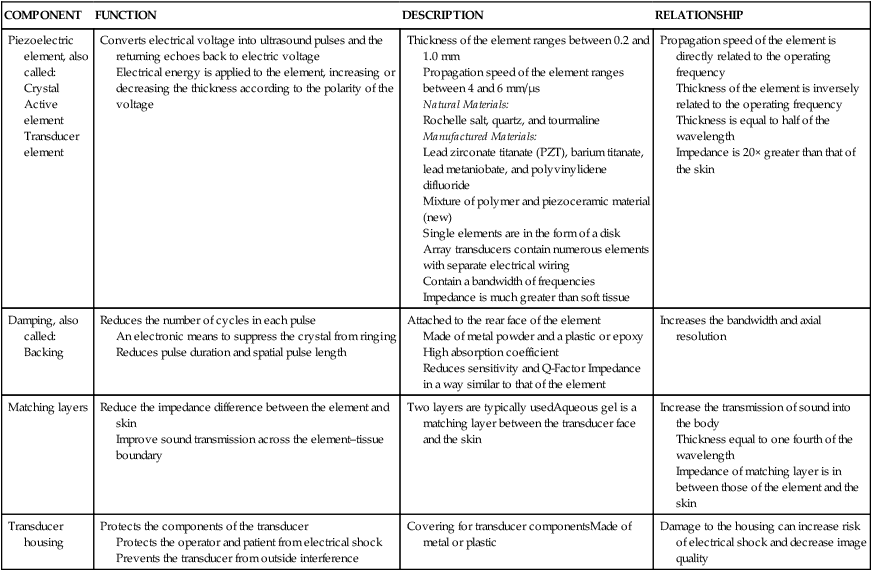
COMPONENT
FUNCTION
DESCRIPTION
RELATIONSHIP
Piezoelectric element, also called:
Crystal
Active element
Transducer element
Converts electrical voltage into ultrasound pulses and the returning echoes back to electric voltage
Electrical energy is applied to the element, increasing or decreasing the thickness according to the polarity of the voltage
Thickness of the element ranges between 0.2 and 1.0 mm
Propagation speed of the element ranges between 4 and 6 mm/μs
Natural Materials:
Rochelle salt, quartz, and tourmaline
Manufactured Materials:
Lead zirconate titanate (PZT), barium titanate, lead metaniobate, and polyvinylidene difluoride
Mixture of polymer and piezoceramic material (new)
Single elements are in the form of a disk
Array transducers contain numerous elements with separate electrical wiring
Contain a bandwidth of frequencies
Impedance is much greater than soft tissue
Propagation speed of the element is directly related to the operating frequency
Thickness of the element is inversely related to the operating frequency
Thickness is equal to half of the wavelength
Impedance is 20× greater than that of the skin
Damping, also called:
Backing
Reduces the number of cycles in each pulse
An electronic means to suppress the crystal from ringing
Reduces pulse duration and spatial pulse length
Attached to the rear face of the element
Made of metal powder and a plastic or epoxy
High absorption coefficient
Reduces sensitivity and Q-Factor Impedance in a way similar to that of the element
Increases the bandwidth and axial resolution
Matching layers
Reduce the impedance difference between the element and skin
Improve sound transmission across the element–tissue boundary
Two layers are typically usedAqueous gel is a matching layer between the transducer face and the skin
Increase the transmission of sound into the body
Thickness equal to one fourth of the wavelength
Impedance of matching layer is in between those of the element and the skin
Transducer housing
Protects the components of the transducer
Protects the operator and patient from electrical shock
Prevents the transducer from outside interference
Covering for transducer componentsMade of metal or plastic
Damage to the housing can increase risk of electrical shock and decrease image quality
Types of transducers
Continuous wave
Pulse wave

TYPE
DESCRIPTION
FOCUSING
BEAM STEERING
Convex sequenced array
Multiple elements arranged in a curved line
Operated by applying voltage pulses to groups of elements in succession
Pulses travel in different directions, producing a sector-shaped image
Also called: curved array, convex array, curvilinear array
Electronic
Electronic
Intracavital
Mechanical, linear array, or phased array transducers mounted on probes designed to insert into the vagina, rectum, or esophagus
Crystal is mechanically swept up and down to produce a 45 to 110 degree sector image
High frequency with rapid frame rates optimizing axial and lateral resolution
Also called: endocavital, transcavital
Electronic
Electronic
Intraluminal
Extremely small crystal arrays are mounted on the end of a catheter designed to insert into a fetal, vascular, or anatomical structure (i.e., umbilical cord, artery, fallopian tube)
High frequency (10 to 20 MHz)
Also called: transluminal
Electronic
Electronic
Linear sequenced array
Straight line of rectangular elements about one wavelength wide
Operated by applying voltage pulses to groups of elements in succession
Pulses travel in straight parallel lines producing a rectangular image.
Also called: linear array
Electronic
Electronic
Linear phased array
Contains a compact line of elements about one-quarter–wavelength wide
Operated by applying voltage pulses to most or all of the elements using minor time differences
Resulting pulses can be shaped and steered
Received echoes follow the changing position of the pulse
Permits multiple focal zones
Electronic
Electronic
Mechanical
Uses a single element with a fixed focal depth
Produces a sector image
Mechanical
Fixed
Sector
Each pulse originates from the same starting point
![]()
Stay updated, free articles. Join our Telegram channel

Full access? Get Clinical Tree

 Get Clinical Tree app for offline access
