24 Fundamentals of Pediatric Radiology
Introduction
Children have special needs and different disease processes, and thus the diagnostic imaging approaches are also different. Pediatric imaging should be problem oriented. Communication between the referring physician and the pediatric radiologist is encouraged (e-Table 24-1). The essential components of a pediatric imaging facility are listed in Table 24-1.
Table 24-1 Essential Components of Pediatric Imaging
From Osborn LM, DeWitt TG, First LR, et al, editors: Pediatrics, Philadelphia, 2005, Mosby Elsevier.
e-Table 24-1 Role of the Generalist
From Osborn LM, DeWitt TG, First LR, et al, editors: Pediatrics, Philadelphia, 2005, Mosby Elsevier.
Imaging Modalities
Pediatric diagnostic imaging can be achieved by various modalities (Table 24-2). X-rays are used in conventional radiography, computed radiography (CR), fluoroscopy, angiography, and computed tomography (CT). Gamma rays are used in nuclear scintigraphy and positron emission tomography (PET). Ultrasonography uses inaudible sound waves ranging in frequency from 1 to 20 MHz to produce images, whereas magnetic resonance (MR) images are generated with a strong magnetic field and radiofrequency (RF) pulse. The digital age has provided us with picture archiving and communication systems (PACS). A PACS eliminates the use of films, permits rapid retrieval of images and remote viewing, and compacts storage.
Table 24-2 Advantages and Disadvantages of Imaging Modalities
| Modality | Advantages | Disadvantages |
|---|---|---|
| X-ray film | Fast; relatively inexpensive; available | Uses radiation; poor soft tissue contrast; two-dimensional imaging only |
| Fluoroscopy | Real-time imaging; relatively inexpensive; available; useful in operating room; can be portable | Uses radiation; no cross-sectional imaging |
| CT | Readily available; excellent delineation of bones, soft tissues, and calcification; multiplanar and 3D reconstruction; minimally invasive (CT angiography); assists in interventions | Intermediate to high radiation dose; relatively expensive; IV contrast side effects (nephrotoxicity and anaphylaxis); weight limit |
| MRI | Excellent soft tissue characterization; no ionizing radiation; multiplanar imaging; minimally invasive (MR angiography); functional imaging; assists in interventions | Less readily available; expensive; claustrophobia often a problem; lengthy exams; limited use in unstable patients; may need sedation/GA; metal artifact; contraindicated with cardiac pacemakers and some devices; gadolinium-induced nephrogenic systemic fibrosis (NSF) in patients with renal impairment; weight limit |
| Ultrasound | Portable; inexpensive machine; real time; least expensive cross-sectional imaging modality; no radiation; differentiates cystic vs. solid masses; multiplanar imaging; Doppler evaluation of blood flow; assists in interventional procedures | Difficult with obese and immobile patients; highly operator dependent; bone and gas obscure anatomy |
| Nuclear medicine | Readily available; functional/molecular imaging | Intermediate to high radiation dose; weak anatomic analysis; may need sedation; radioactive urine and body fluids; expensive |
3D, three-dimensional; CT, computed tomography; GA, general anesthetic; IV, intravenous; MRI, magnetic resonance imaging.
Child-friendly Atmosphere
Environment
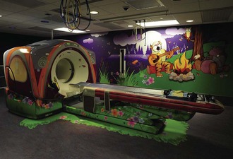
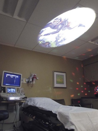
The imaging room’s environment is modified to reduce a child’s anxiety. Smaller equipment can be hidden or concealed with covers and images. Large equipment such as CT scanners can be decorated to give a sense of adventure (Fig. 24-1), and allow study acquisition without sedation. Other distraction techniques include lamps placed in the line of vision of the patient and displaying entertaining images on the ceiling (Fig. 24-2), or the release of piquant aromas in the imaging room (e.g., coconut). Movie goggles allow the child to watch a favorite movie while undergoing magnetic resonance imaging (MRI) or a nuclear medicine scan.
Effective Radiation Dose
Effective dose is expressed as an SI unit, the millisievert (mSv) (Table 24-3). A major benefit of the effective dose is that it permits all radiologic examinations that use ionizing radiation to be directly compared, using a simple common scale. Note that the effective radiation dose of one adult chest radiograph (0.1 mSv) is comparable to natural background radiation for 10 days (background radiation is 3 mSv/year in the United States; people living in Colorado or New Mexico receive about 1.5 mSv more per year than those living near sea level, that is, 4 to 5 mSv/year).
Table 24-3 Estimated Medical Radiation Doses for a 5-Year-Old Child
| Imaging Area | Effective Dose (mSv) | Equivalent No. of CXRs |
|---|---|---|
| Three-view ankle | 0.0015 | 1/14th |
| Two-view chest | 0.02 | 1 |
| Anteroposterior and lateral abdomen | 0.05 |  |
| Tc-99 m radionuclide cystogram | 0.18 | 9 |
| Tc-99 m radionuclide bone scan | 6.2 | 310 |
| FDG PET scan | 15.3 | 765 |
| Fluoroscopic cystogram | 0.33 | 16 |
| Head CT | 4 | 200 |
| Chest CT | 3 | 150 |
| Abdomen CT | 5 | 250 |
CT, computed tomography; CXRs, chest x-rays; FDG PET, fluorodeoxyglucose positron emission tomography; Tc-99 m, technetium-99 m.
Data provided by R. Reiman, MD (Occupational and Environmental Safety Office, Radiation Safety Division [www.safety.duke.edu/RadSafety], written communication, 2006). From Brody AS, Frush DP, Huda W, et al: Radiation risk to children from computed tomography, Pediatrics 120:677-682, 2007.
Radiation Safety
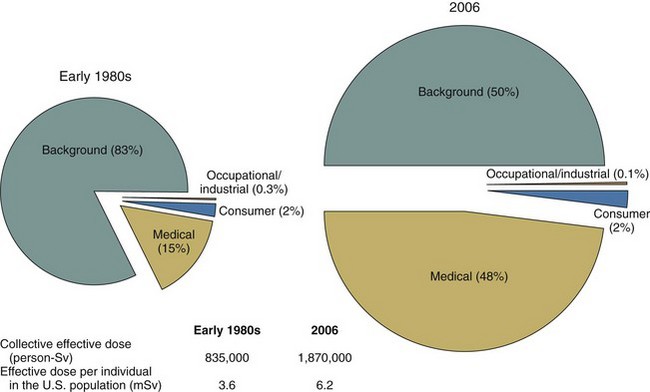
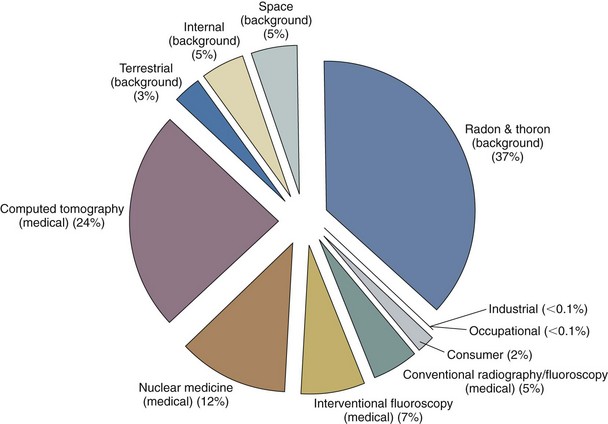
Americans were exposed to more than seven times as much ionizing radiation from diagnostic medical procedures in 2006 than they were in the early 1980s. The increase over the past quarter century puts the cumulative national medical exposures on a level with natural background radiation exposure (Fig. 24-3). The estimated cumulative individual dose from all sources in the early 1980s was 3.6 mSv and in 2006 was 6.2 mSv, almost double the previously reported value. The increase in medical exposure was the only significant change in the two estimates. The largest part of the increase in medical exposure was from CT scans, amounting to almost one half of the imaging exposure, and nuclear cardiac scans, amounting to one fourth of the current total (Fig. 24-4). In 2006 alone, more than 63 million CT scans were performed in the United States. Approximately 7 million CT scans were obtained in children in 2007. Children are at increased risk from radiation because of their greater sensitivity to radiation and a longer lifetime to manifest those changes. To be safe, we should act as if low doses of radiation cause harm using the ALARA (as low as reasonably achievable) principle routinely.
Conservative estimations of potential risk (i.e., any required assumptions are made toward the direction of overestimating risk rather than underestimating it) show that the potential risk of dying from undergoing a CT examination is less than that of drowning or of a pedestrian dying from being struck by any form of ground transportation, both of which most Americans consider to be extremely unlikely events (e-Table 24-2); this provides a comparison of the statistical odds of dying from an abdominopelvic CT examination relative to other causes of death. It can be seen that the lifetime risk of a fatal cancer from all causes is 22.8%, and the lifetime potential risk of a fatal cancer from the radiation associated with a body CT examination is approximately 0.05%.
e-Table 24-2 Estimated Lifetime Risk of Death from Various Sources
| Cause of Death | Estimated Number of Deaths per 1000 Individuals |
|---|---|
| Cancer | 228 |
| Motor vehicle accident | 11.9 |
| Radon in home | |
| Average U.S. exposure | 3 |
| High exposure (1%-3%) | 21 |
| Arsenic in drinking water | |
| 2.5 µg/L (U.S. estimated average) | 1 |
| 50 µg/L (acceptable limit before 2006) | 13 |
| Radiation-induced fatal cancer | |
| Routine abdominopelvic CT, single phase, ∼10-mSv effective dose | 0.5 |
| Annual dose limit for a radiation worker | |
| 10 mSv (recommended yearly average) | 0.5 |
| 50 mSv (limit in a single year) | 2.5 |
| Pedestrian accident | 1.6 |
| Drowning | 0.9 |
| Bicycling | 0.2 |
| Lightning strike | 0.013 |
From McCollough CH, Gimarães L, Fletcher JG: In defense of body CT, AJR Am J Roentgenol 193:28-39, 2009.
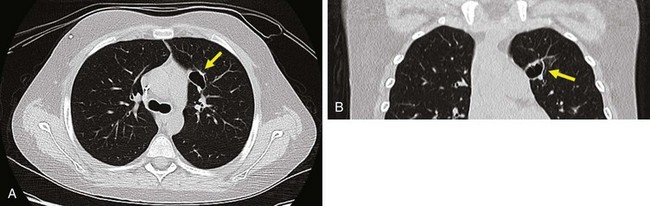
The ordering physician needs to ensure that a CT scan is justified, and the radiologist needs to optimize the scan. Because children are smaller than adults and need less radiation to create the same signal-to-noise ratios, the tube current (milliamperes, or mA) can be greatly reduced when imaging a small child. Other techniques include reducing the peak kilovoltage (kVp); using in-plane shielding for areas such as the eye, thyroid, and breasts; increasing beam pitch; and picking a CT manufacturer that has put effort into dose-reducing technology (e.g., adaptive statistical iterative reconstruction, or ASIR) (Fig. 24-5).
The “Image Gently” Campaign
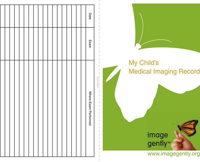
The Alliance for Radiation Safety in Pediatric Imaging has created resources to address the relative risk of CT for children, including parent information pamphlets and a convenient medical imaging record card, similar to the familiar immunization card, for parents to track their child’s imaging history. This card may be distributed by pediatricians or downloaded by parents from the Image Gently website (e-Fig. 24-1). This card alerts families and their doctors to the frequency of patient imaging examinations. With relocation of families and the use of different hospital centers in the same community, this card may help decrease the number of repeat examinations performed.
Radiography
Introduction
Advantages of Radiography in Pediatric Imaging
The advantages of radiography in pediatric imaging include the following:
Physics
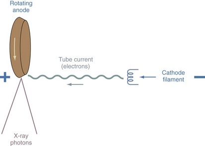
X-rays are a form of short electromagnetic radiation produced by energy conversion when fast-moving electrons from the cathode filament of the x-ray tube interact with the tungsten anode (target) (Fig. 24-6). The amplitude of the tube current (expressed as milliamperes, or mA) depends on the emission rate of electrons from the cathode, which is determined by the cathode temperature. The speed of the electrons as they are propelled from the cathode to the anode is determined by the x-ray tube potential (kilovoltage peak, or kVp). When an x-ray beam is directed toward the examined part of the body, an image is formed. The resultant image is a recording of internal body structures in which the black areas represent the least dense body structures that have allowed the x-rays to pass through (i.e., lungs) and the more dense structures (i.e., bone), which have absorbed the x-rays, appear white (e-Fig. 24-2).
Computed radiography (CR) has replaced conventional film-based radiography. The acquired image is displayed instantly on the high-resolution monitor of the PACS. e-Table 24-3 lists common indications for plain radiography.
e-Table 24-3 Common Indications for Plain Radiography
| Organ System | Indications |
|---|---|
| Head and neck | |
| Chest | |
| Abdomen | |
| Musculoskeletal system | |
| Miscellaneous |
From Osborn LM, DeWitt TG, First LR, et al, editors: Pediatrics. Philadelphia, 2005, Elsevier.
Radiography of the Airway
Lateral Soft Tissues of the Neck
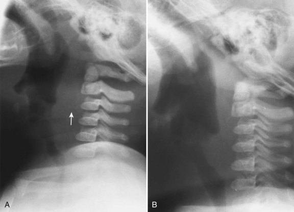
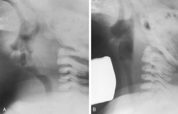
The retropharyngeal soft tissues extend from the adenoids, which are visible by 3 to 6 months of age, to the origin of the esophagus at the level of C4 to C5. A useful ratio is the width of the retropharyngeal soft tissue to that of the C2 vertebral body. The ratio varies in inspiration from almost 1.0 before 1 year of age to 0.5 by 6 years of age. The soft tissue width should not exceed 50% of the accompanying vertebral body to C4 (Fig. 24-7). Expiratory tracheal buckling can create buckling of the trachea anteriorly, causing an apparent increase in retropharyngeal soft tissues and creating a “pseudo-retropharyngeal abscess” (Fig. 24-8). Pseudo-retropharyngeal abscess can be differentiated from a true abscess when the appropriate inspiratory film demonstrates supraglottic airway and hypopharyngeal distention with air (Fig. 24-9). Appropriate patient positioning is critical. The examination of the lateral view of the soft tissues of the neck must be performed in slight extension and during inspiration (Fig. 24-10). The most common cause of a pseudo-retropharyngeal abscess is a film taken during expiration or swallowing, or with an improperly positioned child.
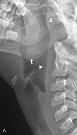
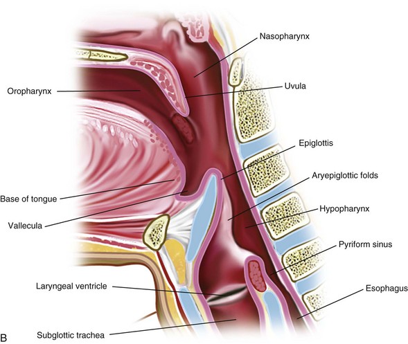
The lateral view of the neck is optimal for evaluating the supraglottic airway (see Fig. 24-7). The lower border of the nasopharynx is the hard palate, soft palate, and uvula. The oropharynx (below the hard and soft palate) leads to the air spaces at the base of the tongue, which are the valleculae. Immediately behind the valleculae is the epiglottis. The hyoid bone is inferior and anterior to the valleculae. The oropharynx also merges posteriorly with the nasopharynx to form the hypopharynx. The tonsils are seen in the lateral walls of the hypopharynx. Anteriorly, the hypopharynx leads to the larynx and becomes the esophagus. The pyriform sinuses are the most lateral and inferior margins and provide a landmark for the level of the vocal cords.
Anteroposterior Film of the Neck
The frontal radiograph is best for evaluation of tracheal position. Normally, the trachea is slightly deviated to the right by the aortic arch (deviation to the left is always abnormal). A normal thymus will not affect the trachea. Expiration causes buckling of the trachea to the right (see Fig. 24-8). Note that the airway is a dynamic system and changes in caliber and position so that an isolated, single film may be quite misleading. Nonetheless, an abnormal configuration of the airway should be pursued in light of the clinical history.
Chest Radiograph
Interpretation of the Chest Film: 1. The Radiologist’s Circle
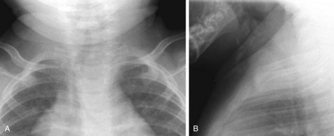
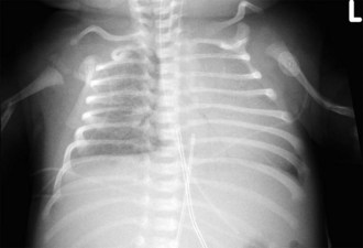
Determine the presence of bowel distention, air–fluid levels, and free intraperitoneal air. The heart and liver are transparent organs; one can see opacities or bronchial markings projecting over their shadows. Then look at bones and soft tissues; one can often see portions of the arms, shoulders, ribs, sternum, and mandible, as well as cervical, thoracic, and lumbar vertebrae. Be alert for fractures (Fig. 24-11), congenital abnormalities (e.g., absent clavicles), bone destruction, or other signs of disease. Examine the soft tissues of the neck, thorax, and abdomen to detect any swelling, foreign body, calcifications, and so on. The soft tissues may reveal multiple artifacts, such as hair braids, buttons, bandages, electrocardiogram (ECG) electrodes, or redundant skin folds. Soft tissue swelling or subcutaneous calcifications can be clues to systemic disease.
Interpretation of the Chest Film: 2. Technical Factors
Determining Rotation
If the patient is well centered on the frontal view: (1) the medial aspects of the clavicles are symmetrical in relation to the midline; (2) the anterior ribs are equidistant from ipsilateral pedicles; (3) the position of the carina approximates the right pedicles; and (4) the two lungs are symmetrical in density. The signs of rotation include asymmetrical clavicles, a difference in lung aeration, heart projected over one hemithorax and not the other, and asymmetrical ribs when relating the anterior rib to the pedicles (see Fig. 24-11). On the lateral view, the ribs are not seen posteriorly in the straight (unrotated) patient. If the patient is slightly rotated, the ribs are shown on each side posterior to the spine.
Thymus
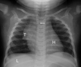
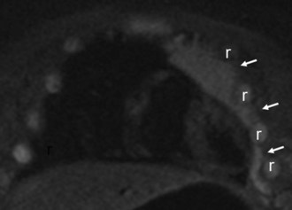
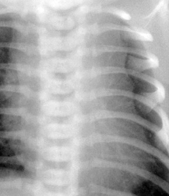
The thymus may make interpreting pediatric chest radiographs difficult. It can simulate cardiac enlargement, lobar collapse, pulmonary infiltrates, and mediastinal masses. The thymus constitutes the major portion of the mediastinal silhouette in a normal newborn. It may extend from the lung apex to the diaphragmatic surfaces; be insinuated into the minor fissure on the right, giving a “sail sign” (see e-Fig. 24-2); and may be bilaterally symmetrical or predominantly one-sided (Fig. 24-12). The normal thymus is a “soft” organ situated in the anterior mediastinum and never “pushes” on the airway or any other intrathoracic structure. The thymus appears smaller as the child becomes older, but the thymus weighs most in adolescents. It is prominent in some children until 4 to 5 years of age, and may persist beyond 5 years, confounding interpretation. Thymic remnants can remain in adults and will be gradually replaced by fat. In an unwell child the thymus can decrease in size and is often not seen. The contour of the thymus is “wavy” because it insinuates itself between the anterior ribs (Fig. 24-13; and see Fig. 24-12).
Effect of Age on the Normal Appearance of the Heart
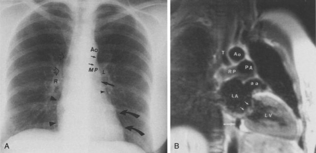
The shape of the heart on plain radiographs changes with the patient’s age. The heart in younger individuals appears more globular in shape, making analysis of specific chamber abnormality difficult. The newborn right heart chambers are larger than the left, and before closure of the patent ductus arteriosus, right-sided cardiac output is greater than left-sided output. This makes identification of the aortic arch difficult or impossible. The right atrial contour in the frontal view and the right ventricular contour in the lateral view will appear abnormally enlarged in these patients. Furthermore, the transverse diameter of the heart is increased, thus increasing the normal cardiothoracic ratio. The thymic shadow regresses by the end of the first year of life, and the heart appears to rotate and descend into the chest. The typical “normal” appearance of the heart does not begin to become apparent until 6 to 8 years of life. However, through adolescence, the apparent size of the main pulmonary artery segment remains increased. Through the teens and early twenties, the size of the main pulmonary artery and base of heart continue to decrease, and the size of the aortic arch increases in caliber, so that by the mid-twenties, the appearance of a “normal” heart may be characterized (Fig. 24-14).
< div class='tao-gold-member'>
Stay updated, free articles. Join our Telegram channel

Full access? Get Clinical Tree


