Fig. 7.1
Abdominal 2D ultrasound: (a) uterine agenesis: ESHRE/ESGE U5b C4 aplasia: vagina (white arrow), absent cervix and uterine body. (b) Transverse vaginal septum/imperforate hymen: ESHRE/ESGE U0 C0 V3: dilated proximal vagina (white arrow). (c) complete bicorporeal uterus and cervical aplasia: ESHRE/ESGE U3b C4: hemicorpora (white arrow)
However, for an accurate evaluation of the much more prevalent but less severe distortions of uterine morphology within the context of congenital malformations, a coronal image of the uterus perpendicular to its long axis is required. The reference image comprises the outer and inner contour of the fundal myometrium and the beginning of the interstitial portion of the Fallopian tubes (Fig. 7.2). Ultrasound imaging is based upon reflection of high frequency sound waves at interfaces between tissues with different characteristics and a distinct endometrial line is necessary to delineate the uterine cavity from the myometrium. The quality of the ultrasound image will be optimal if the endometrium is thick, thus in the secretory or late proliferative phase of the menstrual cycle [2] (Fig. 7.3). If the endometrial echo is not distinct enough, sonohysterography, also called fluid instillation sonography or FIS, will enhance contrast so that the uterine cavity becomes clearly delineated. Saline or gel are negative ultrasound contrast agents, while gel foam containing micro-air bubbles acts as a positive ultrasound contrast agent [11] (Fig. 7.4). Sonohysterography implicates a speculum examination and insertion of a catheter through or in the cervical canal and causes more discomfort compared to a vaginal ultrasound examination only [12]. Sonohysterography isn’t an option if a vaginal approach is not possible or if the woman doesn’t consent to.
Fig. 7.2
Reference plane for uterine morphology assessment
Fig. 7.3
The endometrial line needs to be visible for optimal ultrasound imaging. 2D sagittal image of the uterus: (a) the endometrium is not visible. (b) a well-defined endometrium. (c) contrast enhancement by fluid instilled in the uterine cavity
Fig. 7.4
Coronal image showing the outer uterine contour, the fundal outline of the cavity, the thickness of the fundal myometrium and the beginning of the interstitial segments of the Fallopian tubes. (a) Unenhanced rendered image. (b) Negative contrast enhancement by instilling gel or saline. (c) Positive contrast enhancement by instilling fluid containing small air bubbles (gel foam)
Ultrasound imaging implies cross sections through the uterine cavity and cervical canal as well as through the endometrium, myometrium and cervical wall whereas the outline of the uterus should be visible too. Any change of morphology is to be detected and the underlying cause should be elucidated too: e.g. a fibroid may distort the cavity and/or the uterine contour, an intracavitary structure may be a fibroid or a polyp, and a bulging wall may be due to adenomyosis (Fig. 7.5). A congenital anomaly can be evidenced too. To evaluate the more minor congenital uterine anomalies with 2D ultrasound, success in obtaining the reference image by an abdominal or by a vaginal approach, depends on the position of the uterus (Fig. 7.6). Transverse 2D images of the uterus can usually be obtained and an interrupted endometrial or cervical echo may be indicative of a fusion or a resorption anomaly. But these transverse images do not allow for a detailed evaluation of the degree of altered morphology (Fig. 7.7). With 3D ultrasound technology, the volume can be manipulated and any section through the volume can be made. The reference image can be obtained, irrespective of the position of the uterus in the acquired volume (Fig. 7.8). This explains why 3D imaging is essential for an accurate evaluation of the majority of congenital uterine and cervical anomalies by ultrasound. An important added value of 3D ultrasound is that a volume can be stored and exported allowing for reassessment, discussion and use in training programs. Contrary to 2D ultrasound, laparoscopy or hysteroscopy where one is restricted to the still images or videos taken at the moment of the examination, volume manipulation during off-line analysis allows for an infinite number of additional sections and information.
Fig. 7.5
Ultrasound provides additional information on changes in uterine morphology. (a) endometrial polyp,polyp, (a1) 2D, (a2) 3D-FIS. (b) intracavitary fibroid, (b1) 2D, (b2) 3D-FIS. (c) adenomyosis in the anterior myometrial wall (2D). (d) intramural fibroid and ESRE/ESGE U2b C2: complete septate uterus and cervical septum (3D)
Fig. 7.6
2D coronal image of the uterus: (a) transabdominal image: ESHRE/ESGE U2b, complete septate. (b) Transvaginal image: retroverted uterus, ESHRE/ESGE U0, normal. Full arrow: external fundal contour. Dotted arrow: indentation (a), fundal outline of the cavity (b). X beginning of the Fallopian tubes
Fig. 7.7
Transverse 2D ultrasound does not allow for accurate assessment of the fundal myometrium. (a) Sagittal 2D image. (b) Transverse 2D image: an interrupted endometrial line is visible despite the poor contrast due to a thin endometrial line. (c) 3D coronal rendered image: ESHRE/ESGE classification: the indentation is >50 % of the thickness of the fundal myometrium: U2a C0 partial septate (AFS classification: arcuate uterus)
Fig. 7.8
3D sectional planes and rendered image of a normal uterus ESHRE/ESGE U0 C0. (a) abdominal ultrasound. (b) vaginal ultrasound
How to Obtain the Reference 3D Image for the Evaluation of Uterine Morphology
After having performed a standard 2D evaluation, a 3D volume of the uterus is to be made (Fig. 7.9). The ultrasound probe is hold fixed on a 2D midsagittal or transverse image of the uterus. Especially in case of a wide uterine fundus or an abnormal uterine axis, it may be preferable to start from a transverse image of the uterine fundus (Fig. 7.10). The volume box outline (region of interest) appears on the screen when the 3D button has been activated and the size of the box as well as the sweep angle (usually between 90° and 120°) have to be adjusted so that the volume will include the uterus in full, including the fundal outline. The time of acquisition can be adapted too. A slower acquisition takes more time but results in an better spatial resolution. To evaluate the cervix, one can opt for a separate volume. The quality of the 3D images will be better if this volume is obtained after having enlarged the 2D image so that the region of interest box includes the cervix only (Fig. 7.11). The ultrasound probe is to be hold motionlessly during actual volume capture. It is instructive to pay attention to the sequence of consecutive 2D images of the A plane appearing on the screen during volume acquisition as this gives a first impression of the content of the resulting volume. Once the volume has been obtained, it can be manipulated at once or stored for off-line analysis later and/or elsewhere. Colour Doppler information can be stored during volume acquisition too.
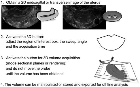
Fig. 7.9


How to obtain a 3D volume of the uterus
Stay updated, free articles. Join our Telegram channel
Full access? Get Clinical Tree
