Micromanipulation station (Integra 3™, Research Instruments Ltd), with parts identified.
Location of the micromanipulation station
Micromanipulation requires complete concentration, and the station should be located in a quiet area of the laboratory, in a position with minimal vibration and away from other activities. Meticulous attention to detail is required throughout, and the embryologist must not be disturbed during a micromanipulation procedure.
Air flow should be minimal; a plastic shield can be built around the station to seclude the activity and also reduce air flow. An anti-vibration platform or marble/granite slab placed on top of multiple squash balls can help to reduce vibration; these should be placed on a solid base, away from doors and elevators. Anti-vibration tables with a platform installed on air cushions for the microscope, separate from the supports for injectors and manipulators, have the advantage that the microscope is free-standing.
The ergonomics of the seating and working position are important; seats should be sturdy and comfortable for both men and women (see Case reports) and at a suitable height relative to the micromanipulator station.
Equipment and supplies
Before selecting micromanipulation equipment, make sure that it is compatible with your existing microscope. Some systems may require an additional fixing plate for certain microscope makes/models. Correct installation is critical: equipment that is not set up and functioning correctly will cascade problems to the micromanipulation procedures. The equipment is usually installed initially by an engineer from the supplying company; it is important to be present at the time of installation in order to learn how the different parts of the system fit together and operate during day-to-day running and maintenance.
Ergonomics and vibration can be a source of problems:
1. A busy lab had two adjacent micromanipulation stations, both fitted onto anti-vibration platforms, but sharing the same benchtop. Using just one of the stations was fine, but vibrations increased for both operators if the adjacent station was in use. The solution was to separate the stations onto two separate benches.
2. Another lab had a station positioned on a workbench that was fixed against a solid wall, with an elevator on the other side. The elevator was used only minimally during the day, but its use increased between 4 pm and 6 pm, when staff began to leave the premises. A solution was either to change the location of the station to the other side of the lab, or to perform the micromanipulations before 4 pm.
3. Similarly, a micromanipulation station was fixed to the wall of a building adjacent to a railroad, with a train passing every 9 minutes. The problem was solved by using very efficient “air cushion” anti-vibration tables.
4. A lab that was staffed by female embryologists found that a small “kneeling” chair for ICSI was very comfortable – however, this was less comfortable for a male embryologist joining the staff!
Microscope
A basic knowledge of microscopy is essential, including a working knowledge of controls and adaptors for passage of light in all microscopes used in the IVF laboratory. The microscope used for micromanipulation will have additional features such as a modulation contrast optical system. Manuals should be readily available and SOPs written to cover the use of all parts of the equipment (see Chapter 2).
A standard inverted microscope with binocular eyepieces of 10× or 15× magnification is commonly used for micromanipulation. The objective lenses vary from a combination of 4×, 10×, 20×, 40× and 100×, and other magnification objectives may be available on request. It is useful to have the objectives fitted in ascending order on the objective turret, so that a clockwise turn of the thumbwheel will increase the magnification in a step-wise fashion. Ensure that the objectives are completely screwed into the objective turret: an objective that is not fully fitted will not provide optimal magnification. Thoroughly clean the eyepieces and objectives when they are in place – a tiny smudge or piece of dirt (even from a fingerprint) can obscure the optics. It is important to be familiar with the different types of objectives; those to be used for micromanipulation techniques must have a long working distance (LW on the objective), because the glass layer of the heated stage is intercalated between the plastic layer of the micromanipulation dish and the lens. The objectives should be plane-linear and achromatic, so that spherical and chromatic aberration is corrected.
Chromatic aberration: light distortion that occurs when a lens fails to focus all wavelengths of light (colors) to the same convergence point. This can be seen as “fringes” of colour along boundaries between bright and dark parts of the image.
Considering the many hours that will be spent using a microscope, spending time and money to ensure a correctly tuned microscope of high optical quality is definitely a worthwhile investment!
An additional 4× objective with a plastic “spacer” tube fitting is available for some micromanipulation rigs. This is a plastic tube of a length that corresponds to the working distance from the highest and lowest point of the fitted pipette, which allows the pipettes to be set up in mid-air above the dish (usually at a height of approximately 14 mm). This has the advantage that pipette tips are less likely to break if set up in mid-air, and the pipette angle can be adjusted so that tips are straight prior to lowering them into the dish. However, always take extra care when lowering the pipettes into the dish for the first time, so that the tips do not touch the base of the dish and break. Remember that the spacer tube is only an approximate guide to the height of the pipette, and may not be the exact distance. Some electric manipulators offer the option of storing positions once the pipettes are correctly installed, including the maximum depth for pipette alignment, so that breakage can be avoided.
Optics
Condensers may be fitted as a turret at the top part of the microscope. Hoffman optics accentuate optical gradients so that the resulting image has different shades of grey. The modulated lighter and darker areas produce a 3-D image, which facilitates micromanipulation. The modulator has a slit design with three zones to control the amount of light transmitted: dark, narrow gray, and clear zones. The condenser turret can be rotated to provide optimal visualization according to the objective in use. This feature is frequently underused, but matching the condenser and objective can improve the micromanipulation procedure.
Hoffman modulation optics have an accessory lens (Bertrand Lens) which can be inserted into the light path above the analyzer. When determining vibration directions or interference figures using parallel or convergent polarized light, this lens is used to bring the image of the interference figures into focus. It is essential to use the appropriate filter for each objective, and each set must be tuned by using the Bertrand filter.
Microscopes with integrated modulation contrast (IMC) are set up so that the orientation of the contrast (direction of the shadow in the 3-D image) is identical for all objectives. This ensures that the spatial impression of the specimen stays the same when changing objectives or magnification. Adjustment of the slit diaphragm is not necessary with IMC.
Nomarski interference contrast optics (also known as differential interference contrast, DIC) uses an illumination technique to enhance contrast in unstained, transparent samples. Light is polarized by a polarizer situated below the condenser, and the polarized light passes through a prism, which causes slight displacement. A second prism and polarizer provide interference contrast, and the resulting shading results in a 3-D image. However, despite the introduction of high-quality plastics, this system can only be used in conjunction with glass-based dishes, and therefore has largely been replaced by the Hoffman system.
If gametes or embryos cannot be clearly visualized in 3-D, the optical modulation settings may need to be adjusted.
Heated stage
Different types of heated stage are available: opaque stages that allow passage of light through them, or metal stages with an aperture for the light source. The stage temperature should be set to maintain microdroplet temperature (and hence the gametes/embryos within them) at 37.0 °C, validated using a thermocouple placed within the microdroplet. The microdroplet temperature will be influenced by the size of the stage aperture (if present), the heat emitted from the light source and the ambient temperature surrounding the equipment (see Chapter 6 for more information on temperature). The heated stage controller should usually be set to a temperature slightly higher than 37.0 °C to compensate for heat loss through the dish base. Heated stage validation should provide an accuracy of +/− 0.1 °C. Some heated stages may be fitted with built-in alarms to provide alert in case of unacceptable temperature variations.
A single temperature setting will suffice only if a single type of dish is used for all micromanipulations. If different types of dishes are used, especially if the material of the dish base differs (e.g. plastic/glass), the heated stage should be reset and revalidated for each dish type (Fig. 11.2). A flow of warmed air below the stage has recently been introduced as an extra feature by some micromanipulation equipment companies, as a means of potentially improving the consistency of heated stage temperature. As with all new innovations, microdroplet temperature must be validated prior to use, to confirm that the air flow does not cause additional evaporation from microdroplets. Since the air flow is below the dish, this should not be an issue as long as sufficient oil overlay is used.
Different types of heated stage may be required for some micromanipulation activities.
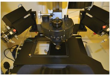
Micromanipulation system with two heated stages, glass on the left, and metal on the right, with an aperture for the microscope objective.
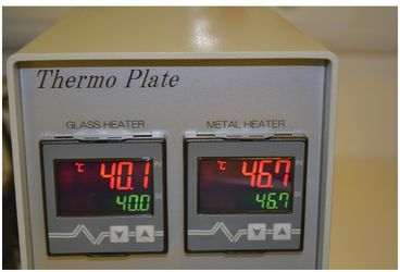
Each stages has a separate temperature controller, which should be validated to ensure that the microdroplet temperature in a dish placed on each stage is maintained at 37 °C. This usually requires different settings for the dual heated stage controller, depending on the ambient air temperature.
Some microscope stages provide additional peripheral areas for resting dishes in between micromanipulations. Make sure that temperature settings on these areas are validated, and take care that dishes are never at risk of being accidently knocked off the peripheral areas.
An X–Y mechanical stage facilitates precise dish placement and movement between microdroplets. The X–Y controls can differ between stages from different companies: it is important to be completely familiar with the controls, since a clockwise turn of the controller from one company may move the stage left, and the same movement on a different controller may move the stage right! Stages with a mechanical insert for dish placement may have a spring mechanism to secure the dish – dishes must be inserted and removed very carefully. Some microscopes have a hinge that allows the neck and condenser to be inclined backwards, reducing the risk of touching the pipettes when dishes are moved away.
Pipette holders
Pipette tool holders (PTHs) secure the pipettes in the system; taking the PTH apart is a useful exercise, in order to understand how it fits together. The PTH is usually loosened at the tip by a counter-clockwise turn in order to fit a pipette. If oil syringes are used, ensure that a meniscus of oil can be seen exuding from the tip before inserting the micropipette. Pass the micropipette gently through the initial opening, and then through an internal “O” ring. There should be a slight resistance as it passes through the “O” ring; do not use excessive force, as this may cause damage.
Resistance may be caused by a blockage: take the PTH apart and check for remnants from a previous pipette that may have broken inside. Passing a small-gauge needle through the lumen should ensure that the lumen is free. Once the pipette is in position, the tip can be tightened via a clockwise rotation. A pipette may sometimes break during installation, in which case the holders must be cleaned and checked to make sure that no glass particles are left inside; these will impair the gentle control of fluid flow required during manipulations. Oil systems can be flushed with the oil in the micro-injectors; air systems can be cleaned by pushing a fine metal wire through the entire length of the holder until the particles are removed.
The pipette tips must be flush with the base of the dish, and the angle in the pipette is therefore crucial. Commercial manufacturers provide Quality Assurance for the angles of their pipettes, but the angles may need slight adjustment for optimal performance in your system. Fitted angle guides for PTHs can help in setting the tool holder angle, but they should be used as a guide only, as the angle may need further adjustment. Angle guides can also be made in-house to facilitate pipette alignment.
Some PTHs are designed so that the complete holder can be moved laterally/outwards from the area of manipulation; this design facilitates pipette set-up and provides easy access to the dish. When familiarizing yourself with this type of micromanipulation station, be careful not to accidentally catch your hand on any fitted pipettes when removing the dish from the stage! Double tool holders are often used for PGD or fragment removal. These are usually set to the same angle; the manufactured angle of the pipettes may differ slightly, and some can be set independently. The angle of the injection pipette (IP) must be absolutely precise; the tip of the holding pipette (HP) is larger, and can tolerate a wider variation in angle. Spending time to make sure that angles are accurately adjusted will make the micromanipulation procedure easier.
Manipulators
Manipulators can be controlled mechanically, hydraulically (usually via oil) or electronically. Each type provides movement in all directions, operating via a system of joints, pivots, and screws. Familiarity with the entire system is essential, in particular knowledge of how each part of the manipulator links to the next. All systems can provide excellent micromanipulation, but each requires appropriate training. Switching between systems may involve an initial period of adjustment, but this should be relatively simple if the basic skills have been learned.
Manipulators position the pipette tips precisely, in the X–Y–Z plane. Their joystick controls can be either hanging or upright. Coarse control allows larger movements, and fine control allows the microscopic movements required during the micromanipulation procedure. The level of control in oil-hydraulic systems can be changed by adjusting the movement ratio. All controls should initially be centered to the midpoint of their scales, to allow leeway in all planes. Complete familiarity with the manipulator controls is essential before starting any micromanipulation procedure.
Oil-hydraulic systems have better control, but may be prone to drift, particularly if there is any strain on the tubing. Always make sure that the controls are centered before each new procedure, with a little slack in the tubing.
More recent models include memory buttons that can auto-store pipette position and individual microdroplet position in the dish; these “extras” can potentially reduce the time needed for each micromanipulation. Digital images and procedure timing can also be recorded. Piezo-assisted ICSI has been reported (Takeuchi et al., 2001), but its use to date is more applicable for animal models.
Syringes
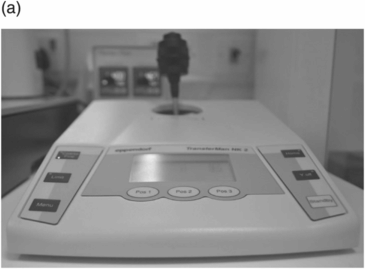
Pneumatic (air) (Fig. 11.3) and hydraulic (oil) syringes are commonly used for micromanipulation in ART, and each system has its own advantages/disadvantages. Oil systems must be completely free of bubbles, from the syringe and throughout the tubing. The syringes are easily filled and topped-up via a two-way screw. Electronic microinjectors may be used to inject fixed volumes in pronuclear micromanipulation for transgenics (Fig. 11.4).
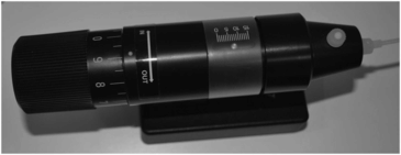
Eppendorf CellTram Air syringe for micromanipulation, with pneumatic manual microinjector.
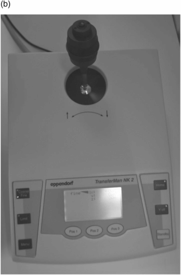
Two views of an electronic micromanipulator system (Eppendorf TransferMan®). This system provides X–Y–Z coarse and fine control, and can also store and recall pipette positions.
Micropipettes
Micropipettes vary in angle and lumen size, and IPs may be spiked or not spiked; the type of pipette used is a personal choice. Keeping a variety of IPs of different lumens in stock for all micromanipulation procedures is beneficial (see Case report, Box 11.2). All micropipettes are very fragile, and great care is needed in removing them from their packaging – make sure that you are familiar with the safest way to do this. Check each pipette to ensure it is not broken: breakages most frequently occur at the tip. Companies do their best to ensure safe packaging and delivery, but there may be a batch with frequent breakage. This must be reported to the company so that the source of the damage can be investigated. Never use a broken pipette, even if the damage is minor.
A couple with severe teratozoospermia were scheduled for ICSI. Following sperm preparation, motile sperm were plentiful, but all of the sperm heads were too wide to be aspirated into the injection pipette. Different aliquots from the prepared sperm all contained sperm with the same morphology. Fortunately, the lab had an alternative type of injection pipette with a slightly wider lumen, and sperm could be aspirated after fitting this new pipette (each sperm head could just fit into the lumen). However, when it came to the injection procedure, the pipette lumen was significantly larger than was routinely used, and thus carried an increased risk of damaging the oocyte during injection. Thankfully, all of the oocytes were injected satisfactorily, and the damage rate seen the next day was less than 5%. Interestingly, the fertilized oocytes had two pronuclei of different sizes, with one pronucleus at least twice the size of the other. This was thought to be due to the size of paternal chromatin from each large sperm head.
Laser
Only Class I laser products should be used for clinical micromanipulation, as defined by international laser safety standards (International Electrotechnical Commission – IEC 60825-1). The precision and size of pulses must be carefully selected, to prevent thermal damage to any area of the gamete or embryo where the laser is not directed. A laser fitted to a microscope objective can be used to ablate the zona pellucida in assisted hatching or biopsy, to induce blastocoel collapse prior to cryopreservation (Mukaida et al., 2006), for sperm immobilization (Xu et al., 2007), and to assist fertilization (Woodward & Campbell, 2014). Some laser systems allow the position of pulses to be pre-set along a chosen path that the laser will then ablate automatically.
The laser must be tested to confirm that the pulse is directed exactly at the target location, at correct intensity. Some systems may be prone to drift, and need to be recalibrated before each use: using a black marker pen, draw a cross on the upper surface of the base of a micromanipulation dish. Direct the laser to a specific area of the ink cross and fire the pulse. A “white” ablated area should appear on the cross where the pulse has fired. If this is not exactly on the target position and of the desired size, recalibrate the laser. Proceed to clinical use only when target position precisely matches the actual position.
Stay updated, free articles. Join our Telegram channel

Full access? Get Clinical Tree


