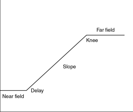
CHAPTER 4 anything not properly indicative of anatomy or motion imaged. binary digit; smallest amount of computer memory. group of eight bits of computer memory. imaging display where the strength of the electron beam determines the brightness. storage of the last several real-time frames. a series of pulses and gaps allowing multiple focal zones and harmonic frequencies. a series of closely spaced reverberation echoes behind a strong reflector. the ratio of the largest to the smallest amplitude that the ultrasound system can handle. loss in intensity from bending of the sound beam at a curved surface. the increase in reflection amplitude from structures that lie behind a weakly attenuating structure. displayed image of the returning echoes. a complete scan of the ultrasound beam; individual image composed of multiple scan lines. the number of complete scans (images) displayed per second. holding and displaying one frame of the real-time sequence. ratio of amplifier output to input of electric power. secondary sound beams produced by a multielement transducer. number of scan lines per frame; scan-line density. denotes the rows and columns of pixels in a digital image. the path toward and away from a reflector are different. disturbance that reduces the clarity of the signal. an expanded image display beyond the normal limits of the transducer. picture element; smallest portion of a digital image. number of picture elements per inch. assigning a brightness value to a missing pixel. the number of voltage pulses sent to the transducer each second. time from the beginning of one voltage pulse to the start of the next voltage pulse. allows access of stored data in an unsystematic order. stored data cannot be modified. two-dimensional imaging of the motion of moving structures. portion of the sound reflected from the boundary of a medium. change of sound direction on passing from one medium to another. multiple reflections between a structure and the transducer or within a structure. redirection of sound in several directions on encountering a rough surface. averaging of frames that view anatomy from different angles. the smallest distinguishable part of a three-dimensional image • One-dimensional (1-D) quantitative image using a single sound beam. • Displays vertically the amplitude of the returning echo (y-axis), and distance is along the horizontal axis (x-axis). • Creates a 2-D qualitative, cross-sectional image using multiple sound beams. • Displays the strength of the returning echoes as pixels in various shades of gray. • The vertical or the y-axis represents increasing depth and the horizontal or the x-axis represents the side-to-side or superior-to-inferior aspects of the body. • Multiple frames per second make up multiple scan lines per frame. • Imaging depth determines when the next pulse is transmitted. • Echo brightness increases with echo amplitude. • Echo position is determined by the round-trip time of the reflector. • Penetration depth is limited by the propagation speed of the medium. • Exact imaging plane cannot be systematically reproduced. • Measurement of structures larger than the field of view is estimated. • Produces ultrasound pulses for each electrical pulse applied. • Receives returning echo reflections, producing an electrical voltage. • Delivers electrical voltages to the memory. • Generates a small voltage signal (radio frequency) proportional to the amplitude of the returning echo. • Radio frequency signals are processed by the system. • Individual signal paths for transmission and reception of the sound beam. • Number of channels equals the number of transducer elements. • In ultrasound, typically 64, 128, or 196 channels are used. • Controlling the characteristics of the sound beam is directly related to the number of channels employed. • Independent pulse delay and element combination constitutes a transmission channel. • Each independent element, amplifier, analog-to-digital converter, and delay path constitutes a reception channel. • Generates the electric pulses to the crystal producing pulsed ultrasound waves. • Determines the pulse repetition frequency, pulse repetition period, and pulse amplitude. • Drives the transducer through the pulse delays with one voltage pulse per scan line. • Adjusts the PRF appropriately for imaging depth. • Communicates with the receiver the moment the crystal is excited to help determine the distance to the reflector. • Receives, amplifies, and modifies echo information returning from the transducer. • Five functions of the receiver: • Mechanism that compensates for the loss of echo strength caused by the depth of the reflector. • Operator adjustable using time-gain compensation or depth-gain compensation centimeter division slide controls (adjusts variable depths of the image). • Provides equal amplitude for all similar structures regardless of depth. • Compensates for attenuation by boosting amplitudes of deep reflections and suppressing superficial reflections. • Near field—area of minimum amplification. • Delay—depth at which variable compensation begins. • Slope—available region for depth compensation. • Knee—deepest region attenuation compensation can occur.
Pulse-echo instrumentation
Display modes
A-mode
B-mode
Real-time imaging
Limitations
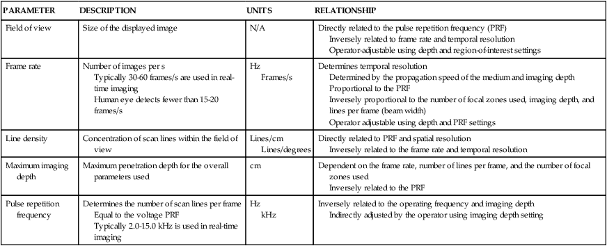
PARAMETER
DESCRIPTION
UNITS
RELATIONSHIP
Field of view
Size of the displayed image
N/A
Directly related to the pulse repetition frequency (PRF)
Inversely related to frame rate and temporal resolution
Operator-adjustable using depth and region-of-interest settings
Frame rate
Number of images per s
Typically 30-60 frames/s are used in real-time imaging
Human eye detects fewer than 15-20 frames/s
Hz
Frames/s
Determines temporal resolution
Determined by the propagation speed of the medium and imaging depth
Proportional to the PRF
Inversely proportional to the number of focal zones used, imaging depth, and lines per frame (beam width)
Operator adjustable using depth and PRF settings
Line density
Concentration of scan lines within the field of view
Lines/cm
Lines/degrees
Directly related to PRF and spatial resolution
Inversely related to the frame rate and temporal resolution
Maximum imaging depth
Maximum penetration depth for the overall parameters used
cm
Dependent on the frame rate, number of lines per frame, and the number of focal zones used
Inversely related to the PRF
Pulse repetition frequency
Determines the number of scan lines per frame
Equal to the voltage PRF
Typically 2.0-15.0 kHz is used in real-time imaging
Hz
kHz
Inversely related to the operating frequency and imaging depth
Indirectly adjusted by the operator using imaging depth setting
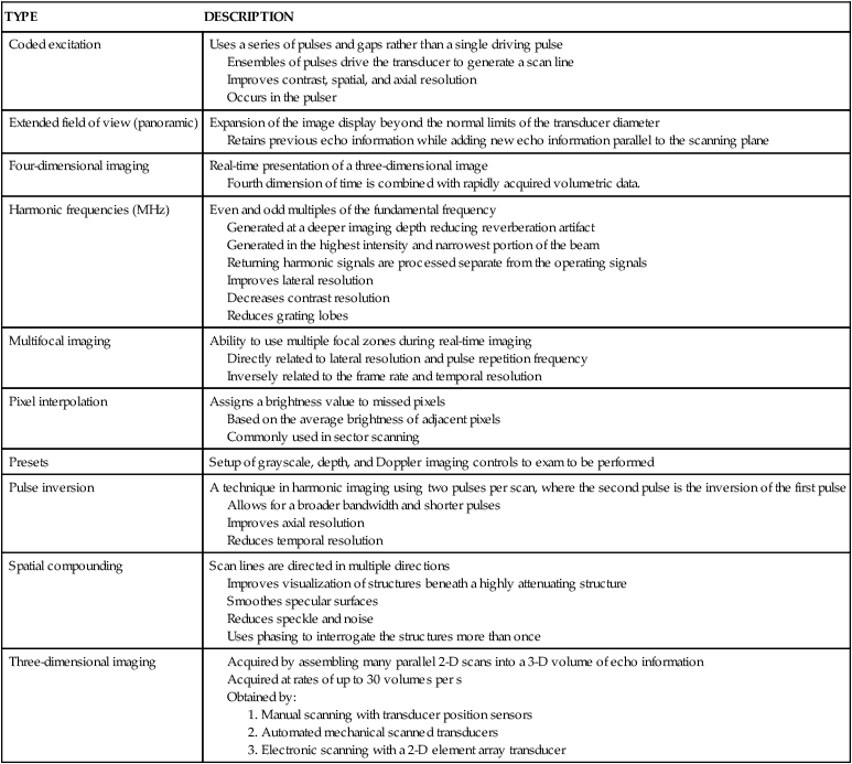
TYPE
DESCRIPTION
Coded excitation
Uses a series of pulses and gaps rather than a single driving pulse
Ensembles of pulses drive the transducer to generate a scan line
Improves contrast, spatial, and axial resolution
Occurs in the pulser
Extended field of view (panoramic)
Expansion of the image display beyond the normal limits of the transducer diameter
Retains previous echo information while adding new echo information parallel to the scanning plane
Four-dimensional imaging
Real-time presentation of a three-dimensional image
Fourth dimension of time is combined with rapidly acquired volumetric data.
Harmonic frequencies (MHz)
Even and odd multiples of the fundamental frequency
Generated at a deeper imaging depth reducing reverberation artifact
Generated in the highest intensity and narrowest portion of the beam
Returning harmonic signals are processed separate from the operating signals
Improves lateral resolution
Decreases contrast resolution
Reduces grating lobes
Multifocal imaging
Ability to use multiple focal zones during real-time imaging
Directly related to lateral resolution and pulse repetition frequency
Inversely related to the frame rate and temporal resolution
Pixel interpolation
Assigns a brightness value to missed pixels
Based on the average brightness of adjacent pixels
Commonly used in sector scanning
Presets
Setup of grayscale, depth, and Doppler imaging controls to exam to be performed
Pulse inversion
A technique in harmonic imaging using two pulses per scan, where the second pulse is the inversion of the first pulse
Allows for a broader bandwidth and shorter pulses
Improves axial resolution
Reduces temporal resolution
Spatial compounding
Scan lines are directed in multiple directions
Improves visualization of structures beneath a highly attenuating structure
Smoothes specular surfaces
Reduces speckle and noise
Uses phasing to interrogate the structures more than once
Three-dimensional imaging
Power
Transducer
Channels
Pulser (transmitter)
Transmit and receiver switch (T/R switch)
Receiver
Time gain compensation (fig. 4-1)
Compression
Pulse-echo instrumentation