(oil and grease)
* Analysis necessary only for carbon dioxide from coal gasification sources.
** If the total sulfur content exceeds 0.1 ppm v/v as sulfur then the species must be determined separately and the following limits apply:
Carbonyl sulfide 0.1 ppm v/v max.
Sulphur dioxide 1.0 ppm v/v max.
Hydrogen sulfide 0.1 ppm v/v max.
*** Analysis necessary only for carbon dioxide from phosphate rock sources.
This conforms to BS4105 Type 2 for food use.
Monitoring gas mixtures
Incubator CO2 and O2 levels can be measured/monitored by physical or chemical methods. Any external electronic device used for CO2/O2 monitoring requires regular calibration, with an appropriate certificate delivered for each calibration. The calibration certificate must include information about the uncertainty range of measurements.
CO2 measurement
Physical methods
Physical methods are currently more popular, and can be highly reliable provided that accurate calibration is carried out.
(a) Electrical resistance (thermal conductivity, TC) is used in the older generation of incubators; the resistance between two sensors (one inside the incubator and one enclosed) is related to the amount of CO2, but depends upon the humidity level in the chamber: >90% humidity is required for precise function, and this is also affected by temperature changes. The monitor must be calibrated in a water-saturated atmosphere, and if the conditions of temperature or humidity inside the chamber change (e.g. after door opening), the sensor cannot give an accurate reading until normal conditions are re-established. This can take 10–15 minutes after door opening/closing, according to the size of the incubator, the amount of water in the humidity pan, etc. If the water pan dries out, CO2 can no longer be measured accurately.
(b) Infrared (IR) sensors use an optical sensor: IR light is emitted, which is absorbed by CO2 in a linear fashion, and the sensor determines the amount of CO2 present according to the amount absorbed by the IR light. This type of sensor is more expensive and has a limited lifespan, but readings don’t require humidity, and CO2 readings recover more quickly after door opening.
Chemical methods
(a) “Orsat Gas Analyzer,” better known as the “Fyrite-Bacharach” analyzer (Fig. 8.1). A manual pump is used to draw gas for analysis into a burette containing a small amount of colored fluid, and the burette is inverted several times to mix the gas and fluid. For ease of calculation, a volume of 100 ml of gas is typically withdrawn. The stopcocks that isolate the absorption burette are used to level the gas in the leveling bottle, and the burette is adjusted to its zero point either by opening a valve or by lowering the scale ruler. This operation is repeated before each measurement. The volume of gas remaining in the burette indicates the percentage of CO2 absorbed. The same technique can be used with pyrogallol to measure oxygen, and with ammoniacal copper chloride to measure carbon monoxide. This method has several pitfalls:
(i) The volume of fluid supplied with the device is sufficient for only approximately 350 measurements, and there is no clear indication when it has been exhausted.
(ii) The rubber bulb of the pump must be squeezed 18 times in order to sample 100 ml of gas: an inevitable source of error.
(iii) The reaction fluids used in the burette are corrosive, toxic, and a source of VOCs: the fluid used in a Fyrite analyzer is potassium hydroxide, a toxic alkaline solution with a red dye added for visibility. These instruments must be handled with great care.
(b) “Draeger Tubes”. This method also uses a manual pump to withdraw gas, and is based on a reaction between CO2 and a solid chemical, with change in color from white to blue (methyl violet):
The Draeger AccuroPump hand pump has a fixed volume of 100 ml – repeated pumping is not necessary. However, leaks in the tubing and a large dead space in the tubing that connects the pump to the incubator are a source of imprecision: the smallest errors are still within +/− 0.5%.
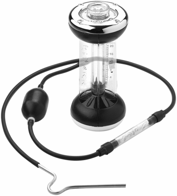
Bacharach gas analyzer; the pink fluid contains potassium hydroxide with a red dye added for visibility.
Oxygen measurement
Three types of oxygen sensors are used in incubators: zirconia (zirconium oxide), galvanic (paramagnetic), and Clark electrode (Fig. 8.2).
1. Zirconia sensors are solid-state, are very precise and don’t require continuous calibration. They measure the difference in oxygen content between the incubator gas and external air, generating a voltage/resistance change according to the difference between the two. The signal output is proportional to the partial pressure of oxygen in the sample gas, with a linear relationship. The sensor element is a ceramic cylinder plated with porous platinum electrodes on the inside and outside. The whole assembly is protected by a metal gauze. Zirconium O2 sensors are usually found on the back wall of an incubator. The porous surface can become contaminated with micro-organisms, and is difficult to decontaminate. If the incubator is powered off with humidity still inside the chamber, they can develop condensation that will affect the function of the sensor.
2. The Clark electrode measures oxygen on a catalytic platinum surface, using the net reaction

The measuring principle is based on an electrical current passing through a cathode and an anode submerged in an electrolyte solution. O2 enters the sensor through a permeable Teflon membrane by diffusion, and is reduced at the cathode, creating an electrical current that can be measured. There is a linear relationship between the O2 concentration and the electrical current; O2 in the sample can be measured after two-point calibration with 0% and 100% air saturation. This type of sensor was very common in the first generation of incubators; regular replacement of the membrane required skilful operation, and the glass electrolyte containers had a tendency to leak frequently. Evaporation of the electrolyte created an additional problem, with formation of a salt crust. The glass electrode was often broken whilst trying to replace the Teflon membrane.
3. Galvanic sensors work on the same principle as the Clark electrode, measuring O2 via its reduction at a cathode. This is accomplished by using two different metals (lead and gold, or lead and silver) in the presence of an electrolyte, so that a voltage relative to O2 concentration is produced. These sensors have a battery, and therefore the sensor must be calibrated periodically to check battery life.
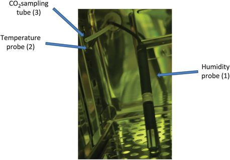
Probes used to monitor incubators. (1) A capacitive humidity probe consists of a hygroscopic dielectric material placed between a pair of electrodes to form a small capacitor. The probe contains a dielectric material (usually plastic or polymer) with a dielectric constant ranging from 2 to 15: when no moisture is present in the sensor, both this constant and the sensor geometry determine the value of capacitance. (2) Temperature probes consist of two wire class A probes. (3) The CO2 sampling system transports a gas sample from the incubator atmosphere to a centralized measuring station (often fitted into the lab ceiling). Samples from several incubators can be analyzed by a single CO2 sensor within a CO2 substation. Sample channels can be measured every 20 minutes. Excess humidity is automatically removed by moisture separators. The internal CO2 sensor is automatically calibrated using outside air (0% CO2) and a calibration gas supply.
Gas cylinder storage
Any errors in delivery of gas supplies to the laboratory can lead to serious problems, and all deliveries must be carefully checked. A secure and safe storage location for gas cylinders, both during use and in storage is essential: this includes all of the gases used in the laboratory, as well as those used by the medical team during any surgical procedure. The storage room, designated as a “No Smoking” area, should be as far as possible from any potential sources of heat or ignition. Different countries have local and national regulations for gas storage areas, which must be adhered to. Specifications generally include:
Adequate ventilation, to prevent gas build-up in case of leakage.
Free of clutter.
Protected from extremes of weather, including high humidity (causing rust and corrosion) and extremes of temperature that will affect gas stability.
Vertical cylinder storage, with the connections uppermost and secured to prevent them from falling, preferably with specific clamps or chains (Fig. 8.3).
It is helpful to store the cylinders in order of delivery, so that the “oldest” cylinders are used first. Inspect each gas cylinder for damage at the time of delivery. It is also prudent to assess the number of cylinders stored at the IVF clinic at any one time, as most companies charge a rental for each cylinder after delivery. Careful assessment of gas usage and frequency of cylinder deliveries can result in significant cost savings: Trigas (5% CO2/5% O2/90% N2) can be a very expensive gas mix. Valves must be closed when not in use, with valve protectors fitted to keep them in place.
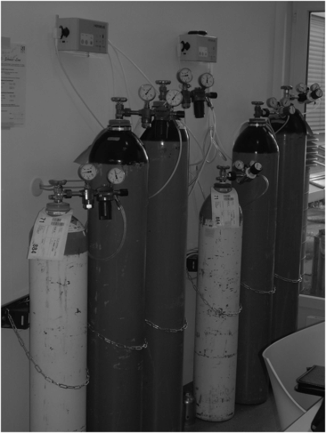
Example of inadequate gas tank storage area; these 100% CO2 and 5% CO2 cylinders were stored within an area of the laboratory, without adequate ventilation and no oxygen sensor to monitor in case of leaks. The cylinders are not stabilized, but held in place with loose chains only.
Safety precautions for gas cylinders
Specification sheets for all gas cylinders contain details of safety aspects relating to the cylinder and the gas, including:
Identification of the gas and the delivery company
Known hazards of the gas
Full composition of the gas supplied
Accidental release measures
Handling and storage
Recommended PPE (Personal Protective Equipment)
Physical and chemical properties
Gas stability and reactivity
Toxicological and ecological information
Disposal, transport and regulatory information.
Asphyxiation is the most common hazard associated with improper use or leakage of gases, and for this reason storage rooms must be well ventilated, and preferably have a low O2 monitor installed. Soapy water can be used to test for leaks. A person suffering from asphyxiation may feel dizzy, or even unconscious. If someone working with gases suddenly becomes dizzy, they should immediately stop what they are doing, and be escorted to an outside area away from the gases to recover and receive medical help. It is always advisable to work in pairs when dealing with gases.
Make sure that is safe to carry or move a gas cylinder before doing so, and wear protective gloves and footwear. A trolley or other device can be used to move cylinders, provided that the cylinder is secured, full training has been given and sloped access is available to avoid stairs. Never attempt to carry a gas cylinder unless you have had proper manual handling training and have carefully assessed the load. Any excessive shock during transit may damage the cylinder: if damage is suspected, contact the delivery company immediately to arrange for a replacement.
Make sure that the cylinder valve is protected at all times, usually by a protective guard; never lift cylinders using the valve guard.
Regulators and equipment for incubator gases
Different cylinders require different regulators; make sure that each type of cylinder is fitted with the correct regulator of appropriate size and pressure rating. The regulator fits directly onto the outlet valve of the cylinder via a screw thread – do not attach any additional tubing between regulator and cylinder! Turn the gas cylinder off fully and make sure that the regulator is fully “screwed out” before fitting, so that no gas flows through the regulator when the cylinder is turned on. Check that the cylinder is supplied with a non-return valve, so that the regulator can prevent backflow that might contaminate the gas supply.
Inspect regulators routinely to make sure that they are not old, and are fit for purpose. They should fit onto the cylinder thread with minimal resistance, and must not be ‘adapted’. Never force a regulator onto a cylinder – if force is required, there is a problem. Do not use a regulator if the thread is loose-fitting or appears to be damaged. Use of polytetrafluoroethylene (PTFE) tape as a temporary connection is not reliable, and is not recommended. Never use an oil or lubricant to try to ease a regulator fitting if the thread is too tight – some gases may react violently with lubricants. If there is the slightest problem with a regulator, seek advice from the company that supplied the regulator, the cylinder, or the incubator.
A manifold can be used to connect several cylinders to a single regulator in order to supply an incubator with a mixture of gases (Fig. 8.4a). Two cylinders can be fixed to a common outlet via an auto-changeover manifold, so that if one cylinder empties, the regulator will switch to the fuller cylinder (Fig. 8.4b). The embryologist must be completely familiar with the function of the manifold, and ensure that one full cylinder is always connected. Switch the regulator manually after each change of empty cylinder, and check the system every day, inverting the handle in the middle. If this is neglected, both bottles will empty in parallel, leaving no “reserve” gas. Also check that the pressure inlet for the cylinder and regulator are correct for the incubator they are connected to, and that the correct gas has been supplied: some incubators can operate from either 100% CO2 or 5% CO2: using the wrong gas supply will have disastrous consequences! It is helpful to have a control dish containing media with phenol red indicator, as this will turn yellow in highly acidic conditions (e.g. a 100% CO2 environment) and pink in alkaline conditions (e.g. an environment where there is no CO2).
Manifolds that allow two gas cylinders to be fixed to a common outlet.
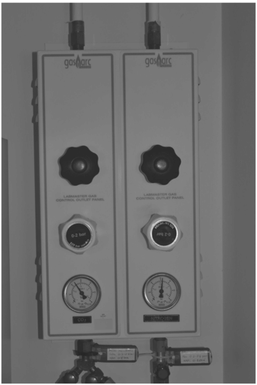
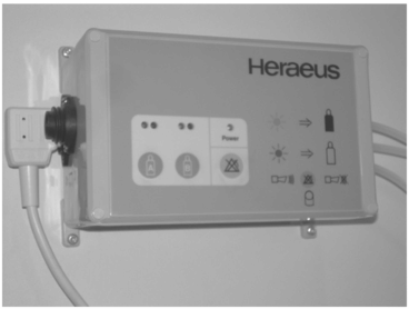
Two regulators supplying purified gas (CO2 gas on the left; N2 gas on the right) to a low oxygen incubator.
Ambient air quality
Air conditioning systems
Air cleanliness is classified according to the number and size of particles within a sample of air, measured in particles per cubic foot or cubic meter of air. The US Federal Standard 209E defines air quality based upon the maximum allowable number of particles 0.5 microns and larger per cubic foot of air: Class 1, 100, 1000, 10 000 and 100 000. The lower the number, the cleaner the air. The ISO 14644-1 classifications are defined as ISO Class 1 to 9 (ISO14644-1:1999). Cleanest, ultra-pure air is Class 1 (Table 8.4).
| ISO class | Number of particles per cubic meter by size in microns | ||||||
|---|---|---|---|---|---|---|---|
| 0.1 micron | 0.2 micron | 0.3 micron | 0.5 micron | 1 micron | 5 microns | ||
| ISO 1 | 10 | 2 | |||||
| ISO 2 | 100 | 24 | 10 | 4 | |||
| ISO 3 | 1000 | 237 | 102 | 35 | 8 | ||
| ISO 4 | 10 000 | 2370 | 1020 | 352 | 83 | ||
| ISO 5 | 100 000 | 23 700 | 10 200 | 3520 | 832 | 29 | |
| ISO 6 | 1 000 000 | 237 000 | 102 000 | 35 200 | 8320 | 293 | |
| ISO 7 | 352 000 | 83 200 | 2930 | ||||
| ISO 8 | 3 520 000 | 832 000 | 29 300 | ||||
| ISO 9 | 35 200 000 | 8 320 000 | 293 000 | ||||
Laboratory air quality can be maintained by using positive air pressure relative to adjacent areas; adjacent rooms with different clean area classification should have a pressure differential of 10–15 pascals, with higher pressure in the most critical area. The position of the air inlet and the dynamics of the heating, ventilation, and air conditioning (HVAC) system are crucial. Unless the source of the air is very clean, an HVAC system can potentially increase the volume of dirty/toxic air brought into the laboratory. This may be particularly important with VOCs that may be embryotoxic.
The location of an IVF laboratory merits careful consideration, including the outside environment; any potential problems need to be assessed specifically for IVF rather than what may be considered “standard” in a hospital setting. Highly polluted air can be man-made (e.g. from traffic/industry/building works) or relate to geography (e.g. from air-borne particles such as desert sand). In such cases, the number of initial external air filters may need to be increased in order to reduce VOCs. Ideally, the air immediately external to the lab should be conditioned to 18–22 °C at 35–55% relative humidity, with a minimum of 15 air changes per hour. The air stream is then processed through activated carbon to remove high molecular weight organics, primarily petrol-derived substances. Potassium permanganate filters can also be used to oxidize lower molecular weight compounds, but should always be used in combination with activated carbon. High efficiency particulate air (HEPA) filters remove only particles smaller than 0.3 µm, not the smaller molecules of pollutants; filters are available to remove VOCs.
Some air purification systems also incorporate UV filters. Parallel streams of HEPA filtered air (laminar flow) blow across the room to expel any dust and particles in the airflow by the shortest route, moving at a uniform velocity of 0.3 to 0.45 meters per second. Air flow can be either vertical down-flow (entering via filters in the roof, exiting through vents in the floor) or horizontal cross-flow (entering through filters in one sidewall and exhausted above the floor in the sidewall opposite and/or recirculated via a bank of filters). Air flow of sufficient velocity over critical areas will sweep particles away from the area, and prevent thermal migration of particles from the laminar flow. At least 20 changes of air per hour are usually required for clean rooms classified as Grade B, C, and D (see Table 8.5).
Stay updated, free articles. Join our Telegram channel

Full access? Get Clinical Tree


